Understanding Data Flow in Mech-MSR Projects
What Is Data Flow?
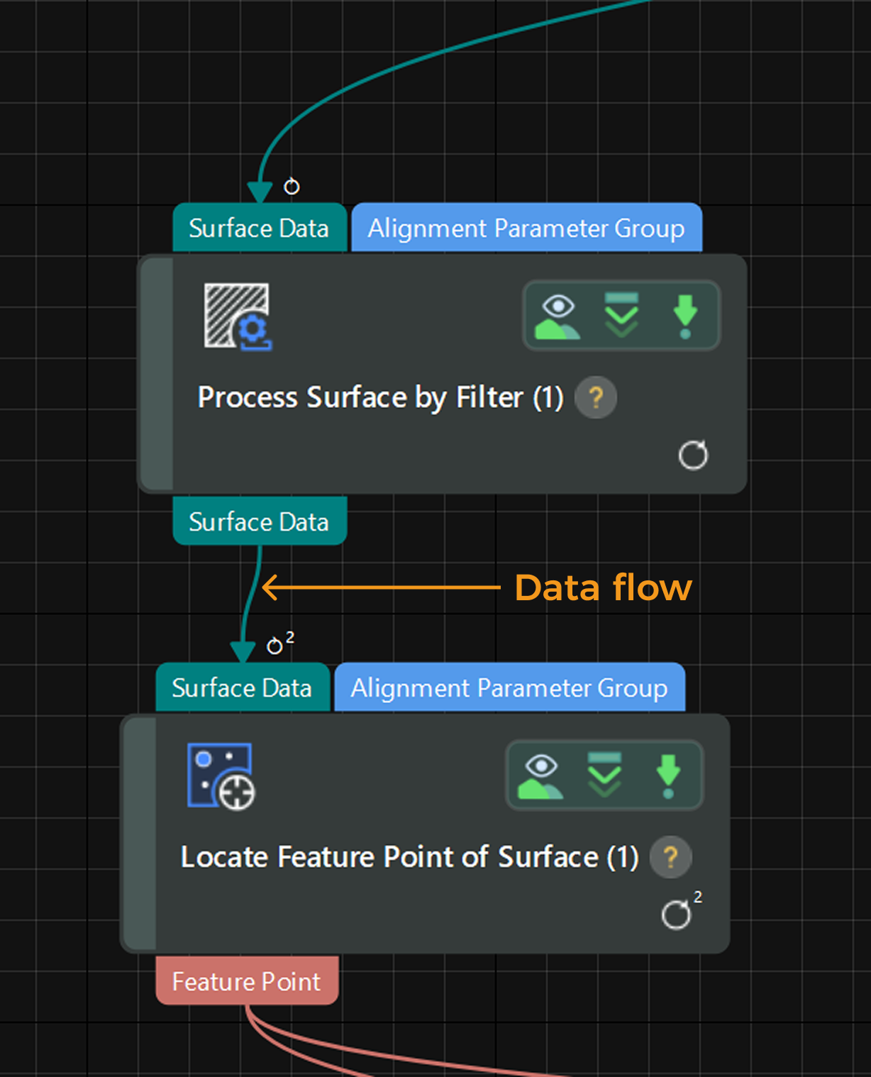
In Mech-MSR, each “Step” represents an algorithmic processing unit that receives input, performs computations, and outputs results. Users can connect multiple Steps through ports to form data flows to process various types of data step by step, ultimately completing the entire measurement and inspection task.
When connecting ports, you must consider two key factors: Data Type and Data Dimensions.
Data Type
In a Mech-MSR project, data type describes the fundamental form of data transferred between Steps, such as Surface (surface data), Profile (profile data), Shape3DList (3D geometric features), and NumberList (list of numerical values). In most cases, the data types of connected ports should match to ensure proper data transmission and processing.
Click here to learn how to view the data types of ports in Mech-MSR
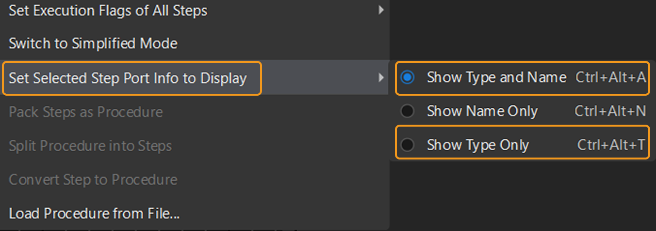
Right-click on a blank area in the graphical programming workspace, select Set Selected Step Port Info to Display, and then choose either Show Type and Name or Show Type Only. The data type will then be displayed on the port.
The name of the port’s data type is enclosed in angle brackets <>, such as <Surface>, <Profile>, <NumberList>, and <Shape3DList>.
In addition, the displayed data type name provides the following information:
-
Suffix
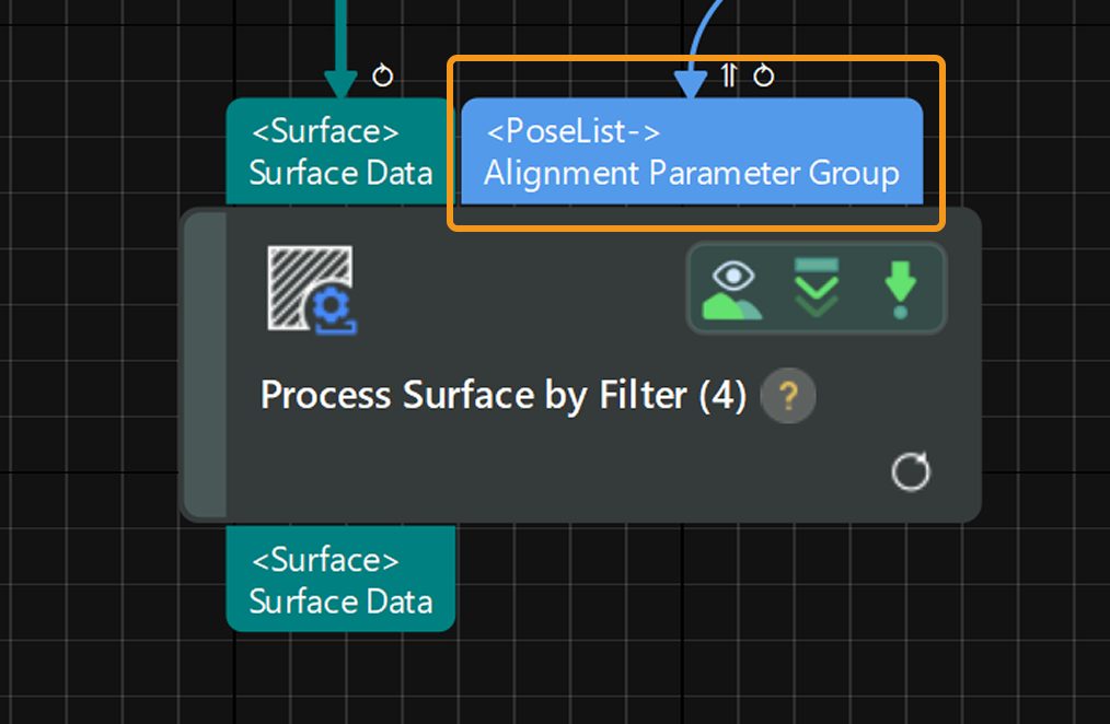
-: Indicates an optional input. For example, many Steps have an input port for the alignment parameter group (PoseList-) that is not mandatory. Leaving this input empty will not affect the execution of the Steps. -
Suffix
[]: Indicates the declared data dimensions of the port. Refer to the Data Dimensions section for more details.
Data Dimensions
In a Mech-MSR project, data dimensions represent the structural levels of the data.
-
Port declared dimensions
Refers to the preset structural levels of data expected by a port, i.e., the dimensions of the data the port expects to receive or output.
Click here to learn how to view the declared dimensions of a port in Mech-MSR
If only the data type name is displayed, it indicates a 0-dimensional structure. Each additional pair of square brackets
[]after the data type name represents an increase in data dimensions.Examples:
-
Surfacerepresents 0-dimensional surface data. -
Surface []represents 1-dimensional surface data. -
Surface [][]represents 2-dimensional surface data.
-
-
Actual input/output data dimensions
Refers to the dimensions of the data actually received or output through the port during Step execution. The actual dimensions may be greater than, equal to, or less than the declared dimensions. See the Loop Depth section for details on how to determine actual input/output data dimensions based on the execution logic of Steps.
In a Mech-MSR project, a Step can receive and output data whose dimensions differ from the declared dimensions. However, the Step may not execute properly, or its output may not meet expectations if the dimension mismatch is not handled correctly.
Framework Loop
When the actual input data dimensions are greater than the declared dimensions of a port, the Step processes the input data level by level based on the declared dimensions. This level-wise execution is called a framework loop.
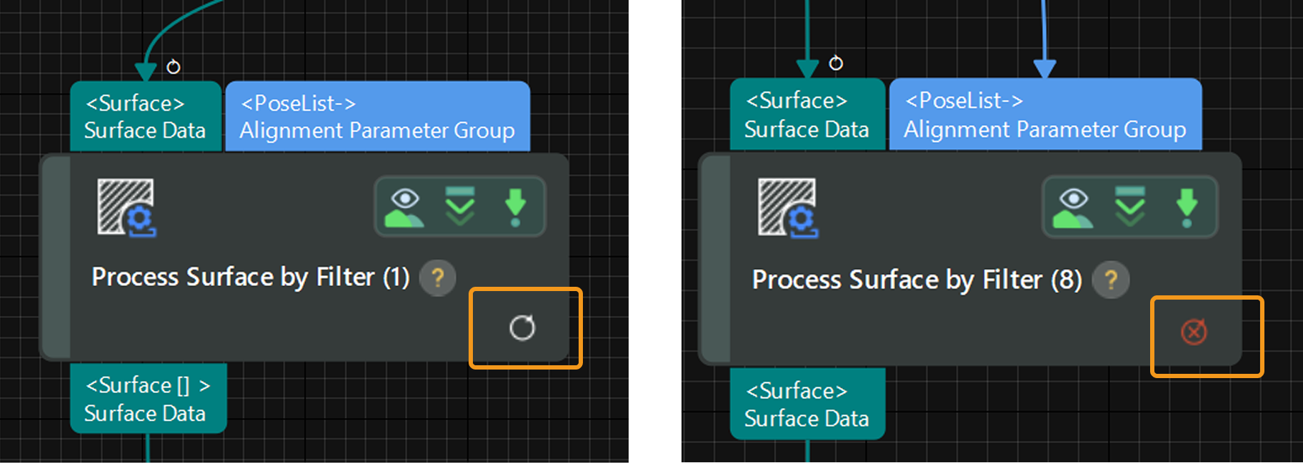
If a Step enters the framework loop mode, a loop icon ![]() will appear in the bottom-right corner of the Step card. The number on the icon indicates the loop depth (the number of looping levels; if the depth is 1, no number is shown). If the current framework loop configuration is invalid or cannot be executed, a loop failed icon
will appear in the bottom-right corner of the Step card. The number on the icon indicates the loop depth (the number of looping levels; if the depth is 1, no number is shown). If the current framework loop configuration is invalid or cannot be executed, a loop failed icon ![]() will be displayed instead.
will be displayed instead.
|
Loop Depth
Loop depth indicates the number of levels over which a Step must loop to process the data at a given port. It is shown above the port by the loop icon ![]() . The number on the icon represents the loop depth (no number will be shown if the depth is 1).
. The number on the icon represents the loop depth (no number will be shown if the depth is 1).
Loop depth is calculated as follows: Loop depth = Actual data dimensions − Declared dimensions. Using this formula, you can also infer the actual dimensions of the input data.
| When multiple ports of a Step receive input, the loop depths across all ports must be consistent. Otherwise, the Step cannot run. |
- Example
-
As shown in the figure below, the input port for surface data in the “Locate Feature Point of Surface” Step displays a loop icon
 , indicating that the data at this port requires the Step to process it through two levels of looping—i.e., the loop depth is 2. Given that the declared dimensions of the port is 0, it can be inferred that the actual data dimensions of the input is 2.
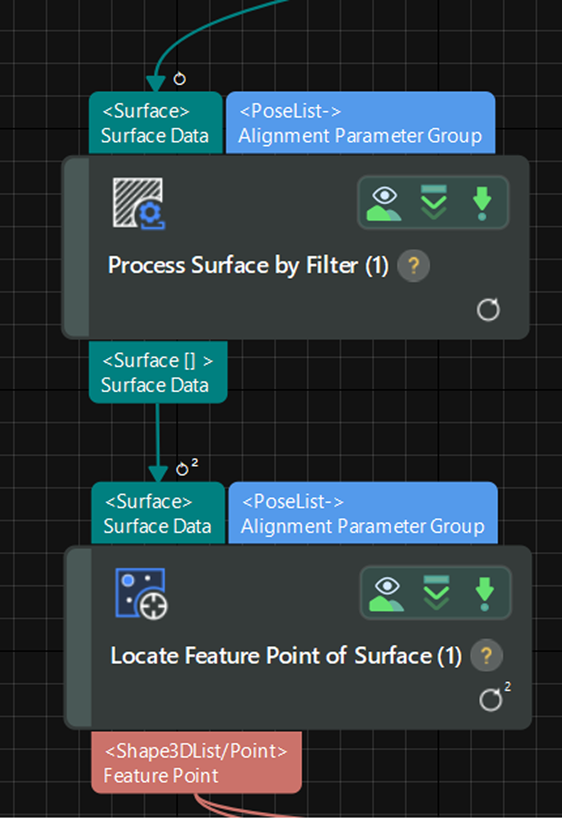
Increase or Decrease Dimensions
If the loop depths of data at multiple ports are inconsistent, you can usually adjust the data at one of the ports by slicing to increase the dimensions or merging to decrease the dimensions, in order to align the loop depths across all ports.
Click here to see where this feature is in the interface
Right-click the data flow and then select Increase Level by Slicing or Decrease Level by Merging to modify the data dimensions.
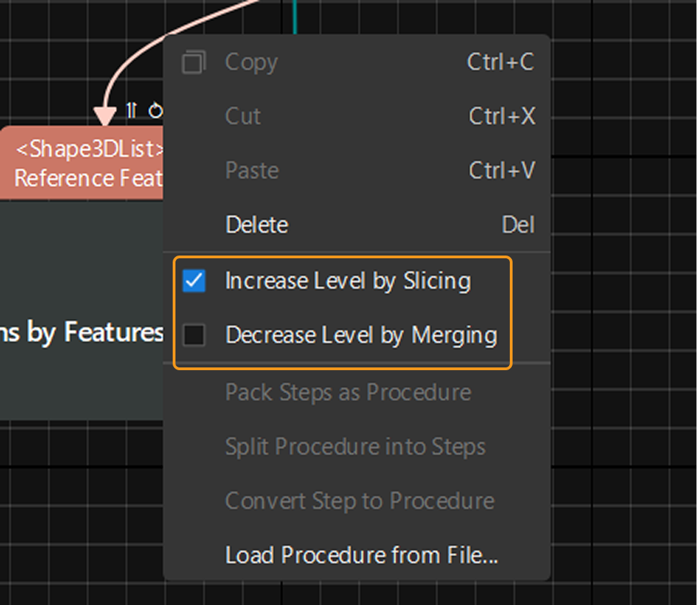
Increase Level by Slicing
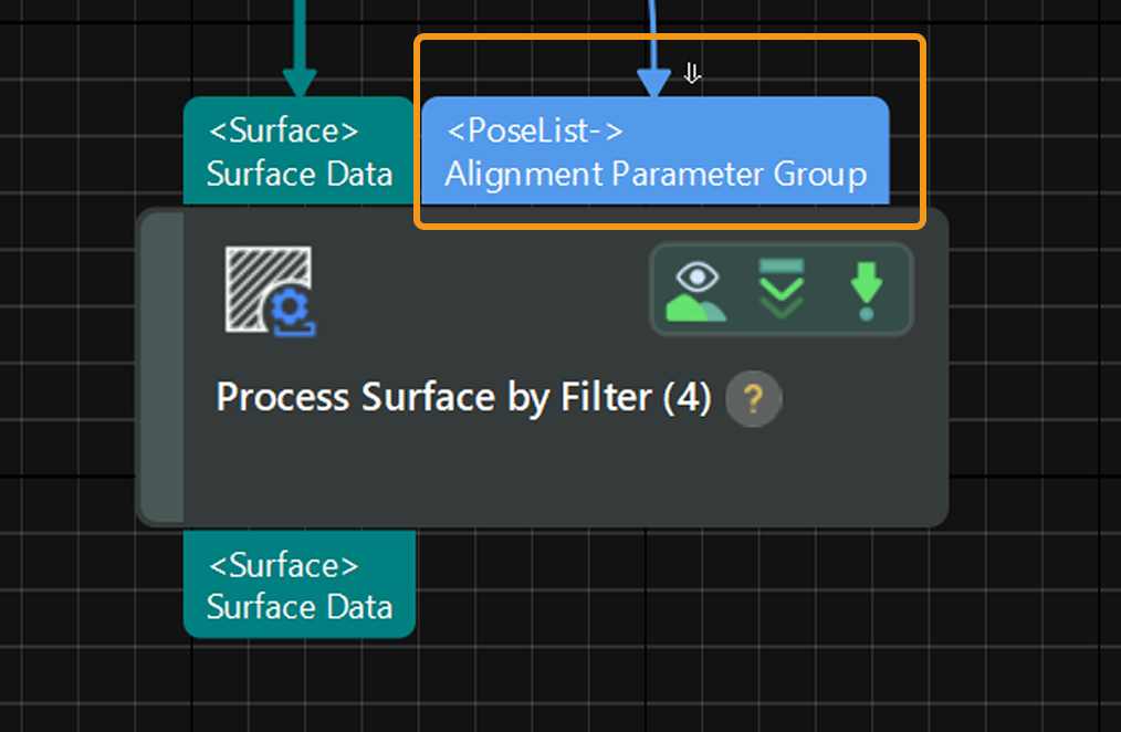
This action increases the data’s dimensionality by one through a slicing operation. After the data is raised in dimension, the dimension increasing icon ![]() will appear above the port.
will appear above the port.
|
Decrease Level by Merging
This action reduces the data’s dimensionality by one through a merging operation that combines multiple data elements. After the dimensions are reduced, the dimension decreasing icon ![]() will appear above the port.
will appear above the port.
|
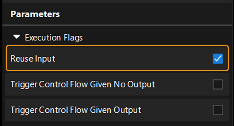
Reuse Input
If the data at a port cannot or does not need to be raised or lowered in dimension, you can choose to reuse lower-dimensional input during Step execution, i.e., Reuse Input. This allows the Step to run properly by repeatedly using the lower-dimensional data. An input reuse icon ![]() will appear above the reused port if the input is reused.
will appear above the reused port if the input is reused.
Click here to see where this feature is in the interface
In the Step’s parameter configuration panel, expand Execution Flags and select the Reuse Input option.
|
- Example
-
Compare a Step’s processing results with the same input, before and after applying operations like dimension increasing (via slicing) or input reuse—the outcomes can vary greatly.
Framework loop?
No
Yes
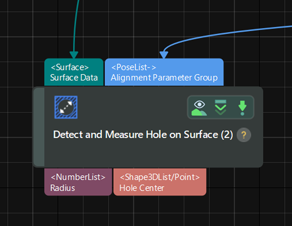
Step input
-
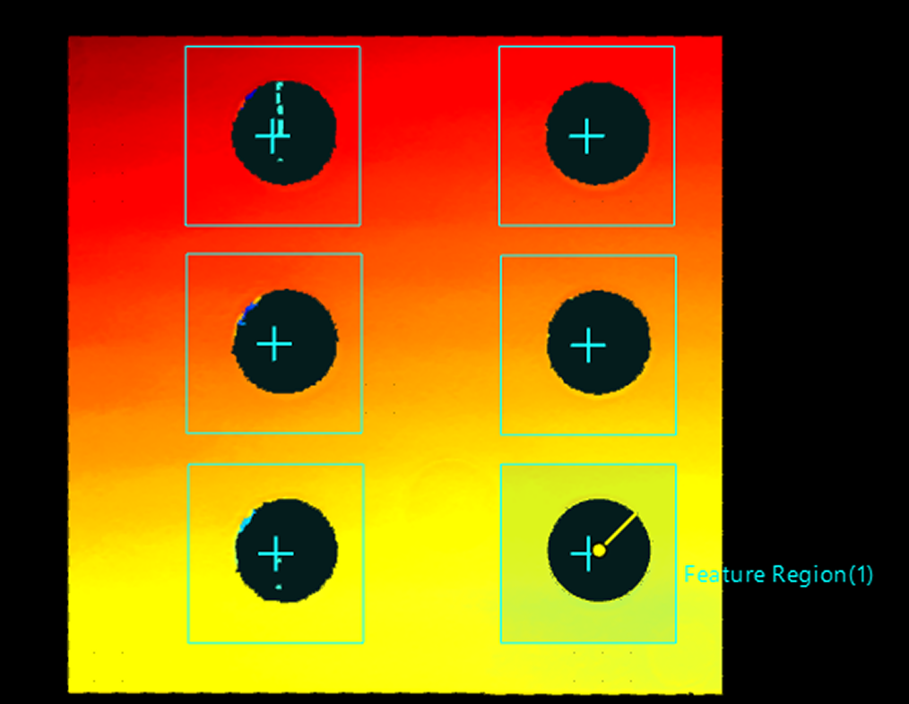
Surface Data: 0-dimensional, image data including holes.
-
Alignment Parameter Group: 0-dimensional, includes the coordinates of six holes.
Operation
N/A
-
Perform Increase Level by Slicing on the “Alignment Parameter Group” to raise the data dimensions from 0 to 1.
-
Select the Reuse Input option for the Step.
Step execution illustration

Step execution results

-
Auto Increase Dimensions
If the actual data dimensions of an input are smaller than the declared dimensions, the system will automatically raise the dimensions of the input to meet the port’s requirement. When the dimensions of the data input into a port are automatically increased, the icon ![]() will appear above the port. The icon displays the number of increased dimensions (no number will be shown if the data’s dimensionality is raised by one).
will appear above the port. The icon displays the number of increased dimensions (no number will be shown if the data’s dimensionality is raised by one).
Currently, only the Extract Data and Merge Data Steps allow you to modify the declared dimensions of ports via the Dimension parameter in the parameter configuration panel. If the actual dimensions of the input data are lower than the declared dimensions, the system will automatically increase the dimensions of the input.
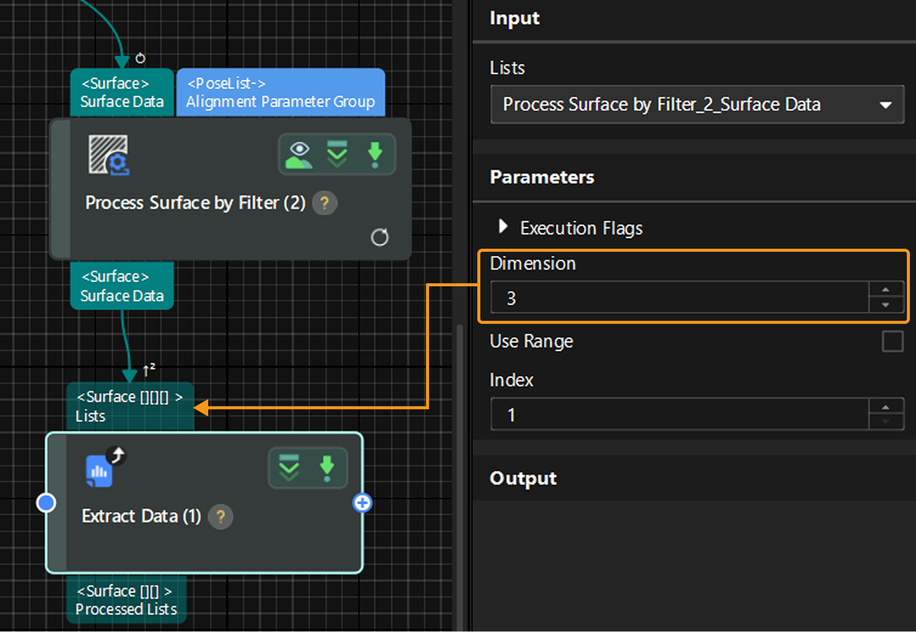
| Unlike dimension increase via slicing, the automatic dimension increase raises the data dimensions by packing, rather than slicing it into multiple elements. |
Top-Level Dimensions
The input port of the Accept All Step does not have fixed declared dimensions. Instead, it directly accepts upstream data and adopts its dimensions as the declared dimensions. This is referred to as top-level dimensions, indicated by the icon ![]() above the port. The port’s data type will also reflect the actual dimensions of the received data.
above the port. The port’s data type will also reflect the actual dimensions of the received data.
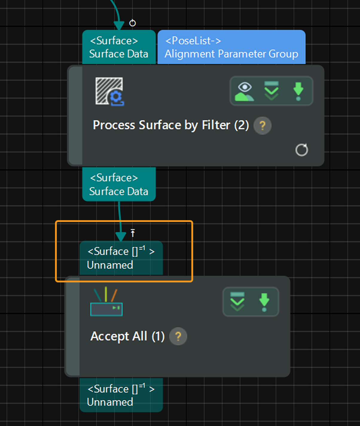
| The Accept All Step can also be used as a quick way to inspect the dimensions of given data. |
Troubleshooting
Loop Depth Mismatch
Symptom:
When running the project or a specific Step, a pop-up appeared stating that “Loop depth mismatch: ....”
Solutions:
-
Reuse input: If the data input into a port is not an array (list), select Reuse Input under “Execution Flags” in the Step’s parameter section.
-
Reduce dimensions: If the port data requiring a higher loop depth is an array (list), right-click the data flow connection and select Decrease Level by Merging to reduce the data dimensions and achieve a loop depth match.
-
Increase dimensions: If the port data requiring a lower loop depth is an array (list), right-click the data flow connection and select Increase Level by Slicing to increase the data dimensions and achieve a loop depth match.
-
Verify the input data at each port to ensure correctness.
Data Count Mismatch
Symptom:
When running the project or a specific Step, a pop-up appeared stating that “Data count mismatch: ....”
Solutions:
-
Reuse input: If the port data with a lower data count is not an array (list), select Reuse Input under “Execution Flags” in the Step’s parameter section.
-
Reduce dimensions & Reuse input: If the port data with a lower data count is an array (list), right-click the data flow connection and select Decrease Level by Merging to lower the data dimensions, and then select Reuse Input under “Execution Flags” in the Step’s parameter section.
-
If the issue persists, use the Extract Data Step or other methods to match the data count across ports.
Cannot Increase Dimensions via Slicing
Symptom:
Right-clicked the data flow and selected Increase Level by Slicing. When running the Step or project, a pop-up appeared stating “Cannot increase dimensions via slicing: ....”
Possible causes:
-
The input data for this port is not a list.
-
The resulting dimensions exceed the Step’s maximum supported dimensions.
Solutions:
Clear the Increase Level by Slicing checkbox. If there is a loop depth mismatch, refer to the Loop Depth Mismatch issue for alternative solutions. If the issue persists, contact Mech-Mind Technical Support.
Cannot Decrease Dimensions via Merging
Symptom:
Right-clicked the data flow and selected Decrease Level by Merging. When running the Step or project, a pop-up appeared stating “Cannot decrease dimensions via merging: ....”
Possible causes:
-
The input data of this port is already 0-dimensional and cannot be further reduced in dimension.
-
The input data of this port is not a list and cannot be reduced in dimension.
Solutions:
Clear the Decrease Level by Merging checkbox. If there is a loop depth mismatch, refer to the Loop Depth Mismatch issue for alternative solutions. If the issue persists, contact Mech-Mind Technical Support.