Collision Detection Parameters Configuration
Attention
It is required to configure the corresponding collision model before configuring the collision detection parameters, otherwise the collision detection cannot be performed or error messages will appear.
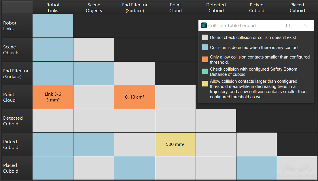
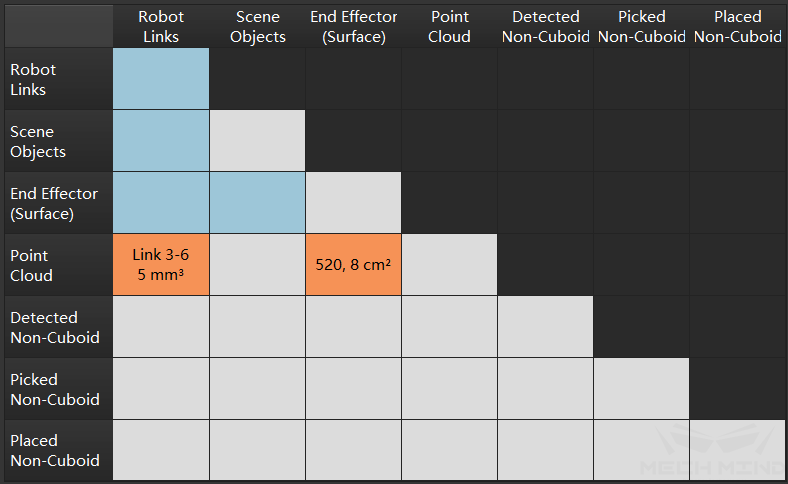
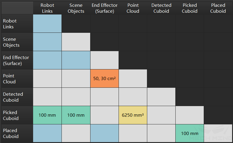
In Mech-Viz, collision detection is performed by detecting the collisions between every two collision models. Therefore, there are multiple types of collision detection combinations, such as collisions between point clouds and other objects, collisions between robots and other objects, etc. In Mech-Viz, you can use the collision table to learn the type of collision detection combination performed by the current project. Different colors in the table represent different collision detection conditions, as shown in the figure below.
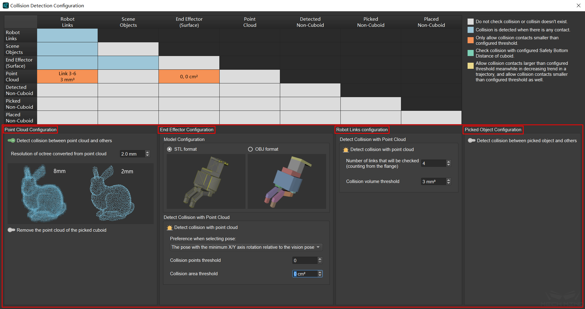
In the collision detection configuration (globally) we have the following four configurations: point cloud configuration, end effector configuration, robot links configuration and picked object configuration, as shown in the following figure. Proper configuration of collision detection can remove unnecessary and redundant collision detection and improve efficiency.
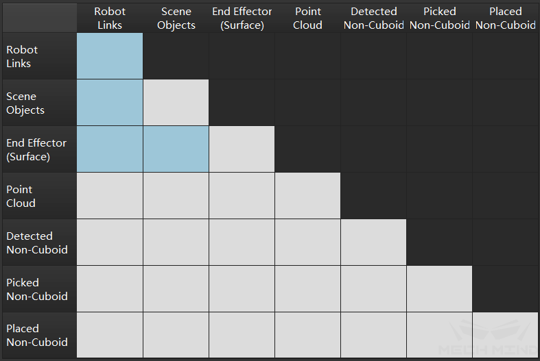
Without any of these four collision detection configurations, only collisions between robot links, scene objects and end effector are performed. This is the default collision detection configuration, and the collision detection performed at this time is scene collision and self collision, as shown in the figure below.
Point Cloud Configuration
If point cloud related collision detection is needed in the project, please turn on the point cloud configuration and set the parameters. The configuring procedure are as follows:
Step 1. Use ![]() to enable or disable point cloud collision detection. When using point cloud collision detection, please make sure that the step “Send Point Cloud to Mech-Viz” is used in Mech-Vision.
to enable or disable point cloud collision detection. When using point cloud collision detection, please make sure that the step “Send Point Cloud to Mech-Viz” is used in Mech-Vision.
Step 2. Set the resolution of octree collision model converted from point cloud. The resolution here refers to the side length of each voxel when the point cloud is transformed into voxels. For the same point cloud, the lower the point cloud resolution, the more the number of voxel cubes, the more accurate the calculation and the longer the time; on the contrary, the larger the resolution, the less the number of voxel cubes, the calculation is relatively rough but the speed is faster.
Attention
When performing point cloud collision detection, what it detects is actually the collision between the end effector and the voxel cube, not the point in the point cloud.
Step 3. Use ![]() to choose whether to remove the point cloud of the picked cuboid.
to choose whether to remove the point cloud of the picked cuboid.
Step 4. Set the parameters of Additional removed length along X/Y axis and Additional removed height along positive Z axis. The length here refers to the additional removal of the point cloud within the length range when removing the point cloud.
Tip
Additional removed length along X/Y axis can not be set too large, otherwise it is easy to remove the surrounding point cloud that needs collision detection.
Additional removed height along positive Z axis can be relatively large to ensure that anomalies caused by point cloud fluctuations can be removed.
After configuration, visual collision detection is introduced. At this time, the collision detection is scene collision, self collision, and point cloud collision, as shown in the following figure.
The above is the method of globally configuring point cloud collision detection. In Mech-Viz, you can also configure point cloud collision detection separately for some movement related Skills. For details, please visit General Parameters of Move Skills.
End Effector Configuration
The collision detection of the end effector is always turned on by default. The configuration of the end effector is mainly to select the tool models in two different formats of stl and obj and the corresponding parameter settings.
The main difference between the two formats is that the stl format only describes the surface geometry of the three-dimensional object, so Mech-Viz only detects the collision between the model surface and the point cloud; while the obj format is used as a combination of multiple solid convex bodies, Mech-Viz will detect both the model surface and internal collisions with the point cloud.
stl format Collision points threshold and Collision area threshold should be set, as shown in the figure below.
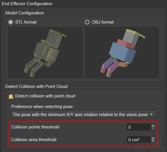
Collision points threshold refers to the number of points that are allowed to collide with the surface of the model when picking.
Collision area threshold refers to the area that allows the point cloud to sweep across the surface of the model in a trajectory.
obj format Only Collision volume threshold need to be set, as shown in the figure below.
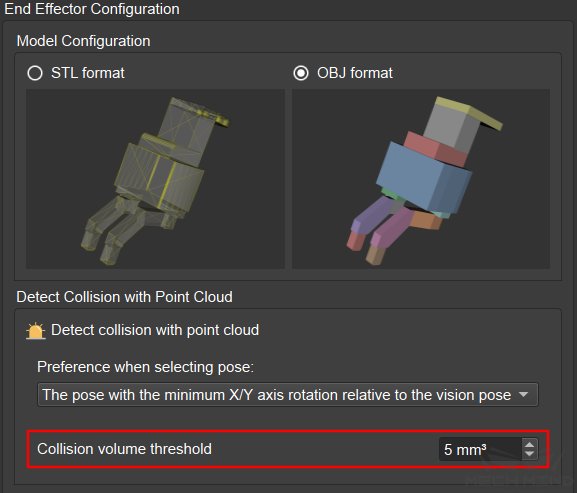
Collision volume threshold refers to the allowed collision volume between the end effector and the point cloud during collision detection.
Preference when selecting pose is a parameter that needs to be set for both formats. It has two options, which are The pose with the minimum X/Y axis rotation relative to the vision pose and The pose with the minimum collision within the X/Y axis rotation range. as shown in the figure below.
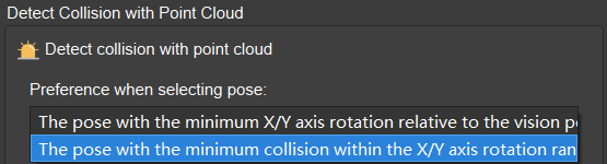
The pose with the minimum X/Y axis rotation relative to the vision pose means that take the sorted pose obtained from the visual movement as the given pose, and check the pose with the smallest X/Y axis rotation relative to the given pose.
The pose with the minimum collision within the X/Y axis rotation range means that calculate all point cloud collisions of the X/Y axis symmetry, and then sort the collisions from minimum to maximum.
Attention
The above two parameters are premised on the existence of symmetry in pose.
Robot Links Configuration
The collision detection of the robot links is on by default. The Robot Links Configuration interface sets the parameters for detecting the collision between the robot links and the point cloud, as shown in the following figure.
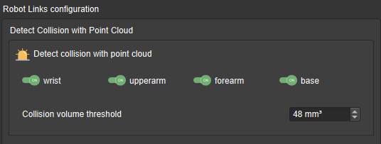
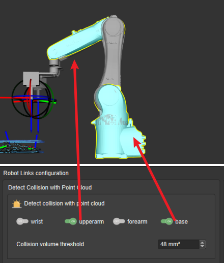
The robot components that may be involved in point cloud collision detection include the wrist, the upper-arm, the fore-arm, and the base. In the Collision Detection Configuration interface, the component(s) that need to be involved in collision detection can be selected. The component(s) selected will be highlighted.
Collision volume threshold refers to the allowed collision volume between the robot and the point cloud when performing collision detection. However, in the simulation, the robot is an STL format model, which means only the collisions between the surface and the point cloud can be detected, so the collision volume here refers to the product of the number of voxels that collide with the robot model surface and the volume of a voxel.
Picked Object Configuration
In the collision detection, the types of picked objects are mainly divided into two categories: cuboid and non-cuboid. The parameters that need to be configured of the two types are roughly the same, and the main difference is the models and the methods of importing. For detailed information, please visit Collision Model Configuration.
Cuboid: When detecting the collision with the point cloud, since the box is a basic geometry, a complete collision can be detected. At this time, the detection content is that the collision between the picked cuboid and the point cloud, and the parameter that needs to be set is collision volume threshold, as shown in the figure below.
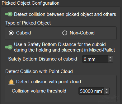
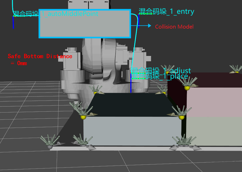
There is also a function “Use a safety bottom distance for the cuboid during the holding and placement in mixed-pallet”. The main purpose is to thicken the bottom of the picked box colliding model, which is used to select a safer trajectory to prevent the box from colliding with placed boxes when moving, as shown in the figure below.
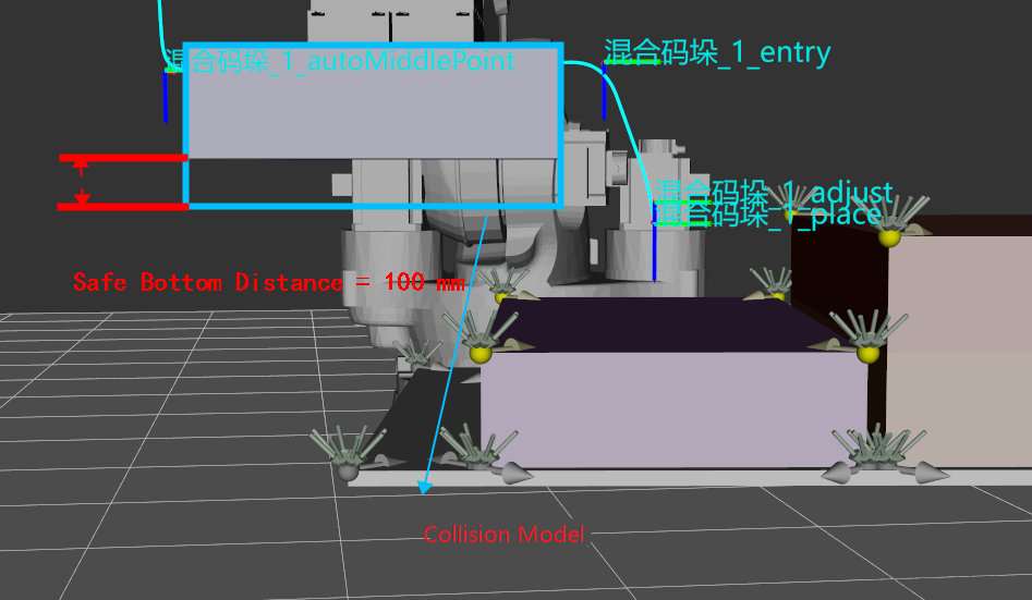
This function is currently only used for mixed palletizing and it must be turned on in mixed palletizing projects. The setting is simple. Turn on the function through ![]() , and then set the safe bottom distance (recommended value is 80mm-120mm).
, and then set the safe bottom distance (recommended value is 80mm-120mm).
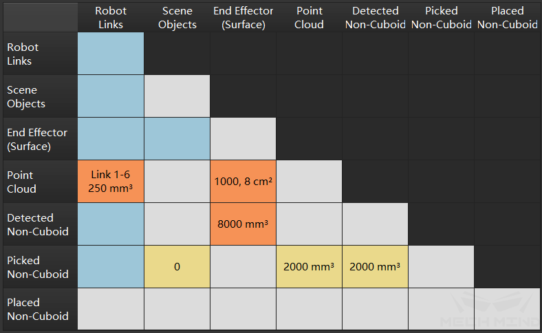
After the setting, the result is a collision detection scene containing the picked cuboid. The collision detection performed at this time is scene collision, self collision, point cloud collision and picked cuboid collision, as shown in the following figure.
Non-cuboid: It is also necessary to set Collision volume threshold, but this threshold is also used to detect the collision between the picked non-cuboid and the recognized objects, so the collision volume with the point cloud of the unrecognized object should be used as the threshold.
In both types of objects, the point cloud of the recognized objects needs to be removed. This function can be turned on through ![]() in Point Cloud Configuration.
in Point Cloud Configuration.
After configuration, the result is a collision detection scene with picked non-cuboid. At this time, the collision detection performed is scene collision, self collision, point cloud collision, and picked non-cuboid collision, as shown in the following figure.