User Interface
The following is a brief description of the software from the perspective of its main components and function implementation.
Main interface
Click the desktop icon to open the main interface of the software (as shown in Figure 1).
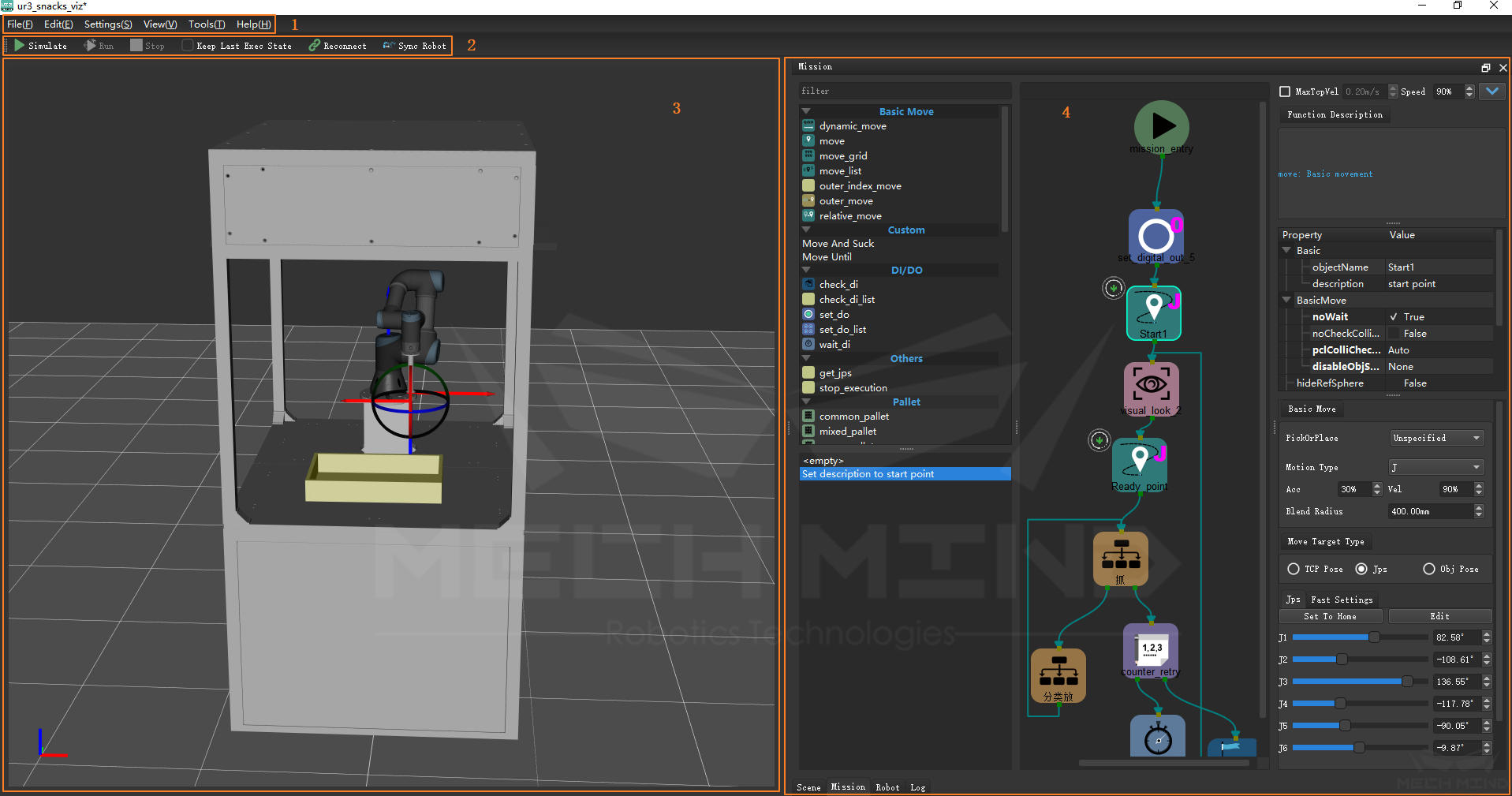
Figure 1 Mech-Viz main UI
The main interface can be divided into
Menu Bar
Control Toolbar
3D Simulation Area
Mission Editing Area
The robot’s movement simulation, actual controlling and graphical programming are realized through the synergy of each area.
3D Simulation
The 3D simulation area is used to display in real time the running status of the robot in real or simulated execution of program, including the robot’s movement trajectory, highlighting of collision prediction, cloud point and pick point both given by vision service.
Scene Object Display
As shown in Figure 2, the 3D simulation area is mainly composed of three parts:
The grid like ground
The imported robot
The imported or created scene model and end effector model
The mouse wheel can be used to zoom in and out of the entire display area. Left-clicking anywhere on the display area and holding down the left mouse button you can drag the scene to adjust the viewing angle of the display area, and holding down the mouse wheel can shift perspective.
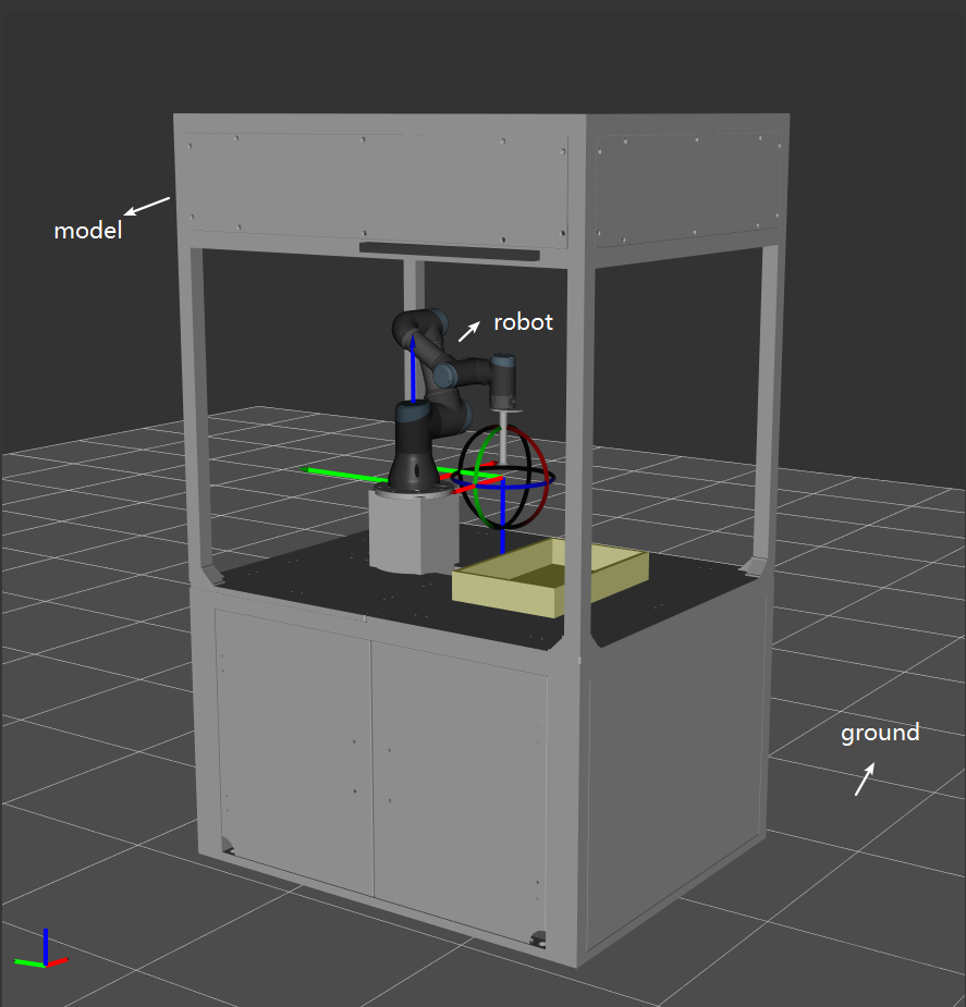
Figure 2 The 3D simulation area
Movement Trajectory Display
Whether in controlling a real robot or in simulation, the 3D simulation area can display the trajectory of the robot. As shown in Figure 3, the user can plan the robot’s movement more reasonably through the simulation trajectory.
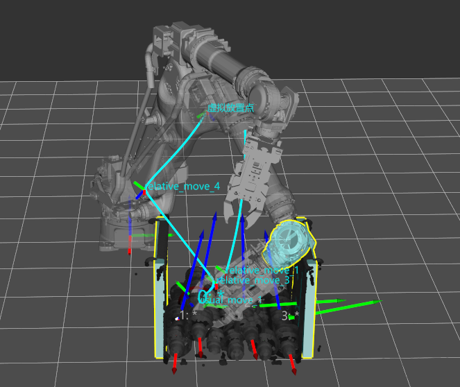
Figure 3 Movement simulation
Collision Prediction Display
As shown in Figure 3, during the task running, collision detection will be performed by the software on the scene objects in the planned trajectory and end-effectors. If a collision is predicted, it will be highlighted in the 3D simulation area and a more reasonable trajectory will be selected to control movement of robot.
Point Cloud and Pick Point Display
The 3D simulation area will update the display of object point cloud and pick point every time after calling the visual service and taking a picture. The displayed information include grabbing order, object’s type, pose and so on.
Mission Editing
The mission editing area is divided into four tabs, namely the Scene tab, Mission tab, Robot tab and Log tab, which can be used to complete the establishment of scene objects, robots and end effectors models, create motion programs with graphical programming, and set or adjust global parameters. The four tab pages can be dragged to adjust the order of display or floated in the screen. The functions of each tab are described below.
Robot Tab
When building a project, you usually start by importing a robot. The robot tab is used to create a simulated robot or operate a connected real robot. As shown in Figure 4, the functions of the robot tab include:
Select a robot. You can select the robot brand and model from the drop-down menu at the top of the page so that the corresponding simulated robot can be created and displayed in the 3D simulation area.
Move a real robot synchronously. When the real robot is connected, it can move to the current pose of simulated robot controlled by Mech-Viz.
Adjusting the pose of a simulated robot. Whether it is a four-axis or six-axis robot, you can adjust the robot’s pose by changing the joint angle or TCP pose.
An end effector model can be imported for display and collision detection, and the center point of TCP coordinate system can be adjusted according to the installation pose of the real end effector.
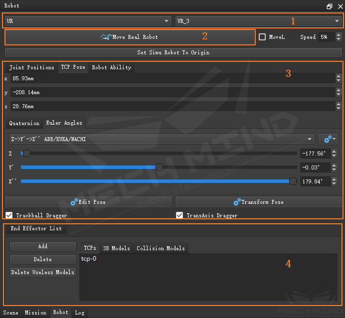
Figure 4 Parameters in robot tab
Scene Tab
The function of the scene tab is mainly to construct the scene where the entire robot works, including the workbench, workspace, etc. As shown in Figure 5,
you can import or create the scene object model and adjust transparency of the model to achieve the modeling of the scene.
In the “Edit Target Object” option, the symmetry and symmetry range of the target object can be adjusted, which is used to plan the optimal trajectory and the grab point with minimum collision during the process of picking and placing.
Ground Grid: By adjusting the height of the scene ground, the relative position relationship of the scene objects can be adjusted.
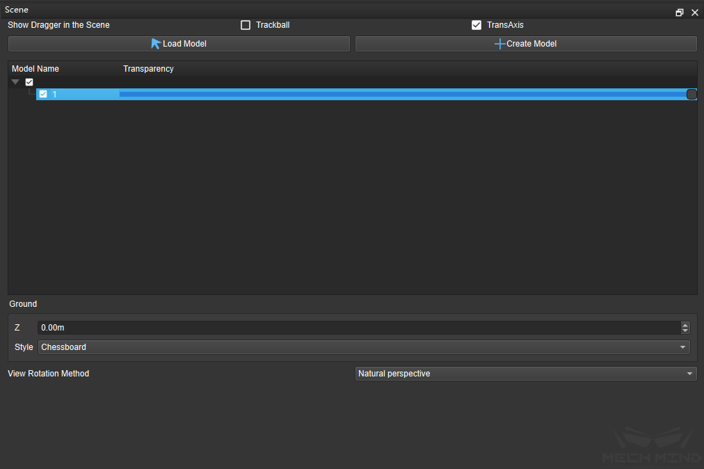
Figure 5 Main functional areas in scene tab
Load Model : you can load the model file in the stl, dae format.
Create Model : you can create a simple model in the Scene directly.
Mission Tabs
You can program for the robot in the mission tab
As shown in Figure 6, it consists of module list, graphical programming workspace, and parameter panel.
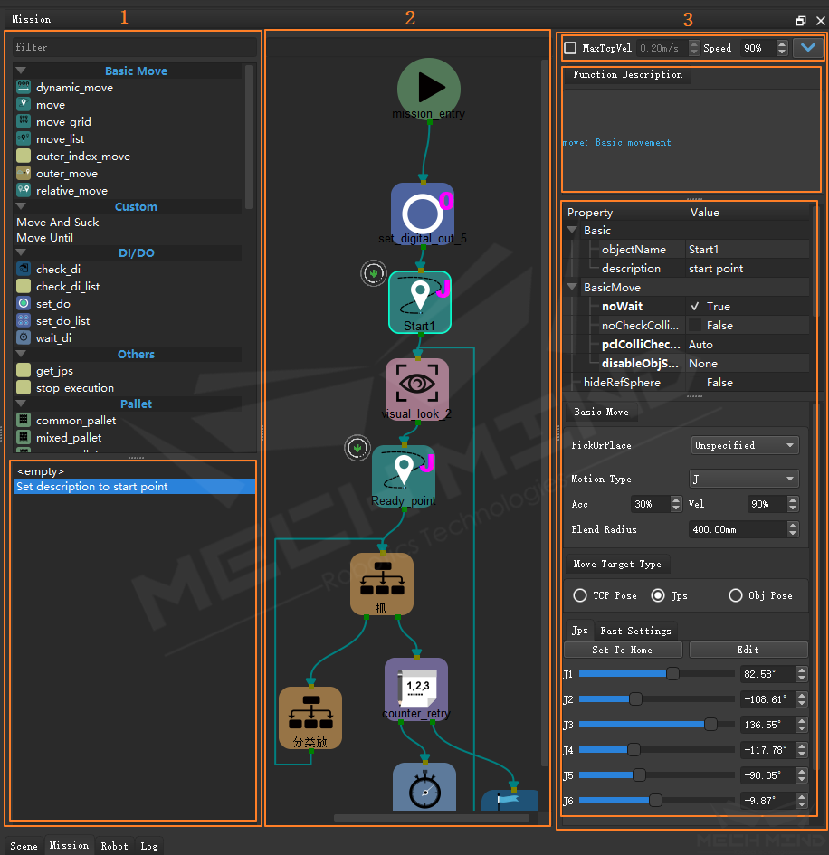
Figure 6 Main functional Areas in Mission Tab
There are many modules in the module list area, which have variety of functions. Drag a module to the programming area, then set the parameters of this module in parameter panel area, you can drag more modules as needed, after that, connect those modules, a program is complete.
The operational history will be shown in the lower part of the module list area, which make it more convenient to debug.
The programming area is mainly used to arrange the corresponding programming modules and connect them in a certain order to achieve the programming. As shown in Figure 7, each programming module has an input port (small brown square) and an output port (green small square). After clicking the output port we can get a connection line and drag the connection line to the next module input port to implement the connection of programming modules.
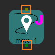
Figure 7 Input and output port of module
Select a module in programming area, the brief introduction and the parameters of this module will shown in the parameter panel, you can adjust this module’s parameters in this area. Meanwhile, you can also set the global parameters such as: collision checking and runtime config in this area. More details about glocal parameters setting, please see Tabs
Control Toolbar
The control toolbar is used to realize the simulation of the robot’s program and control the communication as well as connection with the real robot. The main functions are shown in the table
Icon |
Option |
Description |
|---|---|---|
|
Simulate |
Make the virtual robots perform actions according to designed tasks |
|
Run |
Make the real robots perform actions according to designed tasks |
|
Stop |
Terminate an existing task |
|
Keep Last Exex State |
It is used for debugging the palletizing scene, and continues to stack from the position that has been palletized. |
|
Reconnect |
Establish a connection with Mech-Center to achieve data communication with the robot |
|
Sync Robot |
Synchronize a virtual robot into a pose of a real robot |
None |
Robot Speed |
Adjust the motion speed of robot with the slider or input box |
Keyboard and Mouse Operations
Mouse
Single-Click
Clicking the left mouse button is used to select or activate the button on the interface. When a module is clicked, the module frame will be highlighted and the robot’s pose or palletizing position and palletizing type of the current module will be displayed in the 3D simulation area.
Double-Click
Double-clicking the model in the 3D simulation area or double-clicking the model name in the scene tab will bring up the edit box to adjust the model pose;
For multi-level mission, double-clicking the mission module can expand the lower-level interface.
Right-Click
Right-clicking in the programming area of the mission tab can bring up the interface as shown in Figure 9. It is mainly used for quick operations such as switching up and down levels in multi-level missions, resetting external signal states, and neatly arranging graphical modules;
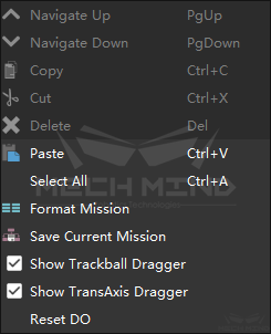
Figure 9 Right-click shortcut menu
When you right-click a module, you can also perform basic operations such as copying and pasting the module.
Mouse Wheel Click
Pressing and holding the mouse wheel in the 3D simulation area can translate the viewing angle of the display area.
Scroll
Rolling the mouse wheel in the 3D simulation area can zoom in and out of the entire display area.
Holding down “Ctrl” and rolling the mouse wheel in the programming area can zoom in and out the display of program.
In the parameter panel, the content of any edit box can be quickly resized by the mouse wheel.
Drag
In any position of the 3D simulation area, holding down the left mouse button and dragging it can adjust the viewing angle of the display area; pressing Ctrl + left mouse button on the dragger to drag can adjust the pose of the robot;
In the mission editing area, holding down the left mouse button can drag the module to any position in the programming area and drag the connection. You can also drag the slider to change the size of each joint angle of the robot or Euler angle in TCP coordinates.
Hot Keys
As shown in the table, the keyboard hot keys are the same as the system.
Hot Keys
Function
F5
Simulate
Ctrl+R
Run
Ctrl+C
Copy
Ctrl+V
Paste
Ctrl+Z
Rollback operation
Ctrl+Y
Resume operation
Ctrl+O
Open project
Ctrl+S
Save project
Delete
Delete
PgUp
To high-level of the multi-level mission
PgDn
To low-level of the multi-level mission
