Fundamentals
Robot
Unless otherwise specified, robot in this article refers to a system of rigid bodies connected by joints, as shown in Figure 1.
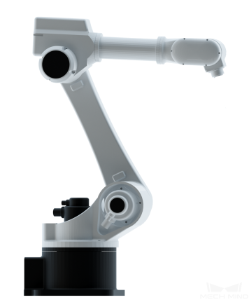
Figure 1. Example of robot
TCP (Tool Center Point)
Robots are usually equipped with end effectors, which are used to interact with objects in the surrounding world. The tool center point (TCP) is the tip point of the end effector. In order to complete tasks such as picking, we usually say that the robot should move to a specific point in space, which actually means its TCP should move to that point.
Joint Position (Jps)
Joint position, commonly known as joint angle, is the position of each joint of the robot. Joint positions are a set of parameters, and the number of sets of parameters equals the number of joint axes. For example, the set of joint positions of a six-axis robot is 6.
Pose
The position and orientation of objects in space are collectively called poses. The pose is expressed in translation and rotation (quaternion or Euler angle). In Mech-Viz, poses are divided into tool pose and object pose, as shown in Figure 2.
TCP pose
The pose of TCP relative to the base of the robot is the TCP Pose.
Object Pose (Obj Pose)
The object pose is the pose of the object’s center relative to the base of the robot. When an object is attached to the end of the robot, the default initial position of the object is the same as the tool pose, but the orientation is opposite. If there is Symmetry or Pick Tool Offset , the relative transformation of the object pose and tool pose may change.
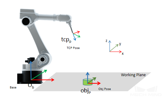
Figure 2. Poses
Attention
The direction of the Z-axis of the object pose must be the opposite of the direction of the Z-axis of the TCP pose during the grasping process.
Forward Kinematics
Forward Kinematics computes the pose of the end effector from given joint angles. When a set of robot joint angles is given, there is only one solution of the tool pose.
Inverse Kinematics
Inverse Kinematics computes the joint angles from a given end effector pose. For a specific tool pose, the corresponding joint angles may have multiple sets of solutions or no solutions.
Pick-Hold-Place
Picking, holding and placing describe the way that robot interacts with objects. These actions are an integral part of applications of symmetry in Movement Tasks and transformation changes/resets between object poses and tool poses.
Picking
The state that robot moves to the pick point pose and controls the end effector to pick the object by changing the output signal is called “picking”. Once the “picking” state becomes effective, the relative position of the object and the robot’s TCP is bonded, and Mech-Viz will plan the robot’s trajectory according to the object’s Symmetry.
Holding
The state after the robot picking up the object and before the object being placed is called “holding”. In the “holding” state, the bound relationship between the object and the robot always exists. This state will take effect automatically after the object is picked, and cannot be configured in Mech-Viz.
Placing
The state that robot reaches the pose of placing and controls its end effector to release object by changing the output signal is called “placing”. When the “placing” state becomes effective, the relative position of the object and the robot’s TCP is no longer bonded.
Symmetry
Each object to be picked has a corresponding object pose. According to the object pose, Mech-Viz will change the tool pose to control the robot to pick, as described in Pose. In practice, objects often have symmetry. For these objects, the robot can pick or place in various ways according to its symmetry angle, and the results are the same.
Symmetry angle is the smallest angle for which the object can be rotated around the X/Y/Z axis to coincide with itself. For example: the symmetry angle of a square is 90°; of a rectangle is 180°; of a regular hexagon is 60°; of a circle or a ring is 0°; no rotation symmetry is 360°, as shown in Figure 3.
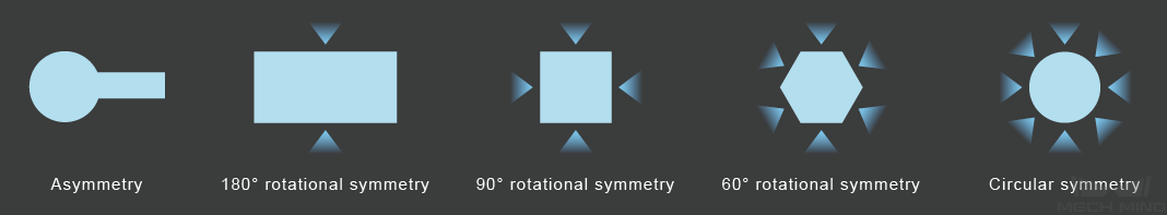
Figure 3. Symmetry angle of objects
Among them, the symmetry around the Z axis is called the strong axis symmetry, and the symmetry around the X or Y axis is called the weak axis symmetry .
weak axis symmetry : Usually, between X and Y axis, the axis with a relative stronger symmetry will be regarded as the weak axis and its symmetry will be used in the actual calculation. For example, if an object has 90° symmetry angle around X axis and 0° symmetry angle around Y axis, the Y axis will be regarded as the weak axis, and therefore the symmetry angle of weak axis is 0°.
Users can set the symmetry of the object and use Mech-Viz to select an optimal trajectory of picking and placing to improve accessibility and reduce the rotation of the end effector.
Symmetry of Object
Object’s symmetry is a necessity for the adjustment of object’s pose. For example, when the symmetry of the object is 180°, the robot can freely pick or place in either “forward” or “backward” direction to reduce the rotation of the end effector, as shown in Figure 4.
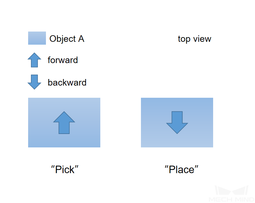
Figure 4. Object Symmetry
The two states of the object can be regarded as the same, and robot can pick in the forward direction and place in the backward direction.
Symmetry of Pick Point
The symmetry of the pick point is related to the way that the end effector picks the object and is used to select an optimal pose of picking. For example, when the object is smaller than the size of a suction cup, the object is picked by the vacuum gripper with offset in order to prevent collision with objects nearby during the picking process. In this case, the object symmetry does not take effect, and the pick point has a symmetrical angle of 180°. You can rotate the pick tool at the initial pick point to “forward pick” or “backward pick”, as shown in Figure 5 below:
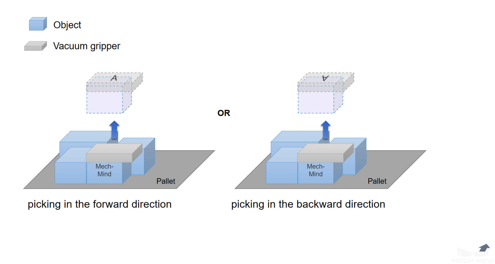
Figure 5. Forward and backward pick
In order to plan the optimal trajectory of movement, Mech-Viz will consider both the symmetry of the pick point and the object during the picking process; and the object pose will be selected according to the symmetry of the object during “holding” and “placing”. For example: when the object is a connecting rod, you can use an adaptive gripper to pick the ring from inside out, as shown in Figure 6 below:
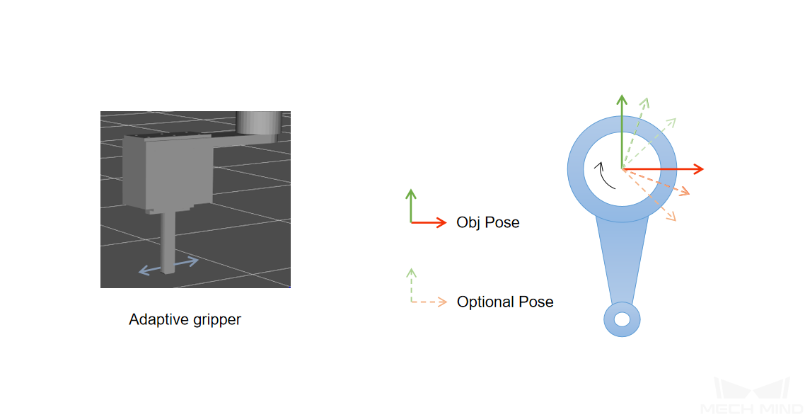
Figure 6. Pick a ring from inside out
The symmetry of the pick point here is 0°, and any angle is optional during picking. Therefore, the symmetry of the pick point should be set with a reasonable trial step size (such as 1°, 10°, etc.). However, since there is no object’s symmetry, if you want to place the object in a set position, Mech-Viz will restore the relative transformation between the end effector and the object during picking.
Pick Tool Offset
When the visual result guides the robot to pick objects of small size or more complex shapes, in order to avoid collision with other objects, the TCP can be offset to a certain point of the object to pick. After assigning the type of tool and strategy of picking, Mech-Viz calculates the value of bias and determines with the point cloud collision to check whether it can be picked or not. As shown in Figure 7.
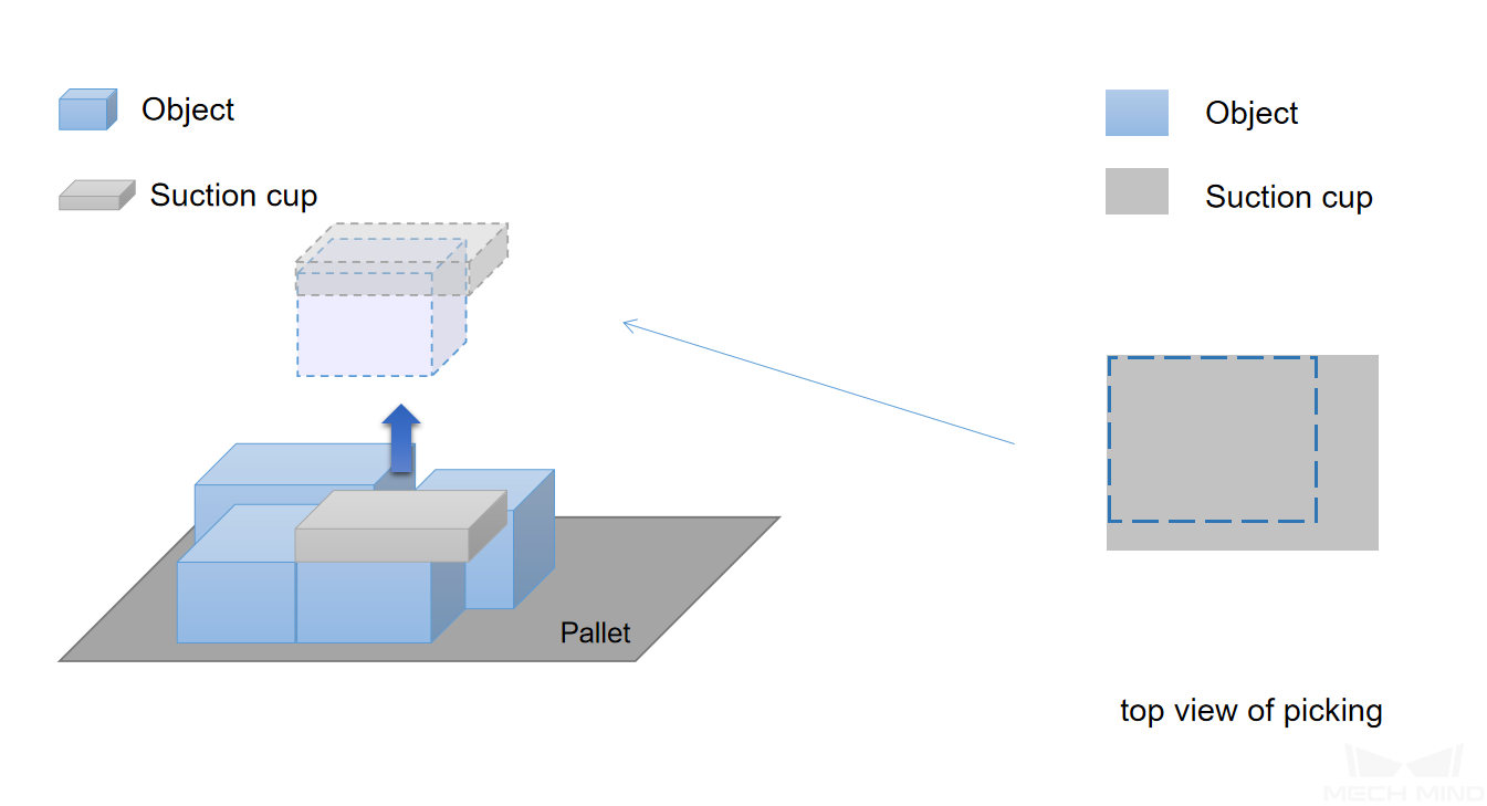
Figure 7. Pick tool offset
Similarly, in mix palletizing tasks, robot can avoid collision with objects nearby with the usage of pick tool offset .
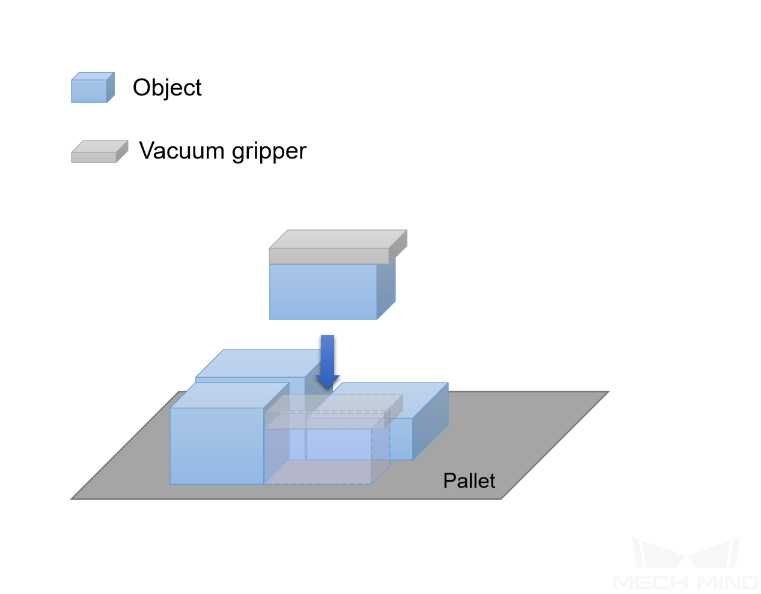
Figure 8. Pick tool offset to avoid collision
Note
For more detail about the using of bias, please see visual_move.
Collision Model Type
There are 4 main types of collision models in Mech-Viz:
Basic geometry (only include cuboid at present): This type of model mainly includes cuboid and end effector which is only loaded with a 3D model but without a collision model in the scene.
Mesh (only include the surface information): This type of model only enables collision detection of the surface. The main models are robot joints and end effector loaded with STL collision model.
Convex polyhedron assembly: This type of model is used as a solid for collision detection, and the main model is an end effector loaded with OBJ collision model.
Octree: The main models are point cloud and the end effector loaded with binvox collision model.