Scene
Scene display settings can be adjusted in the interface as shown in Figure 1.
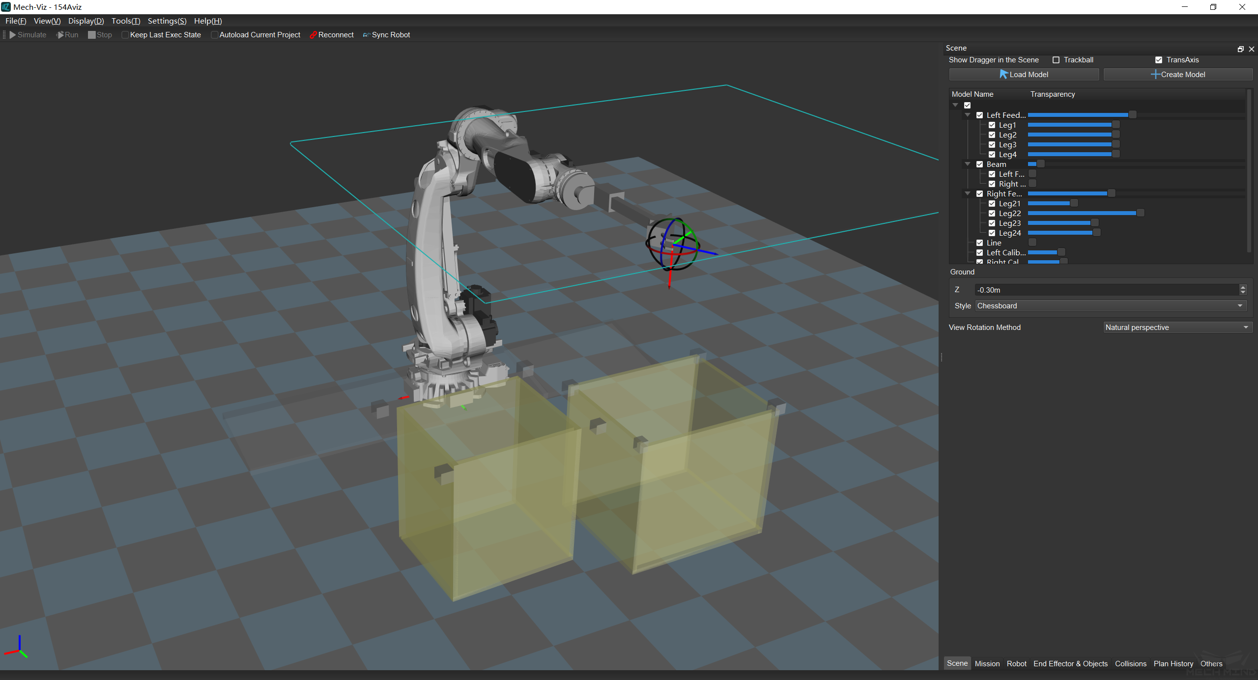
Figure 1. Scene Tab Interface
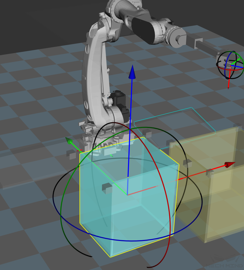
Display the dragger (rotation, translation) of the objects in the scene
Load Model, Create Model:
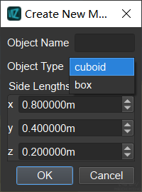
Attention
After loading a new model, it may look larger than the scene. The reason is the unit has not been converted from meter to millimeter. To solve the issue, please double-click the model and scale the model by 0.001 in the model affine.
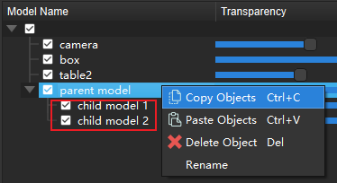
Copy and paste of scene model:
Right-click the model name press shortcuts Ctrl+C and Ctrl+V to copy and paste.
The child model is copied and pasted together with the parent model.
After copying, click on the blank space to cancel the selection, and the model can be pasted in the root directory.
The names of all model copies are concatenated with ‘-1’,’-2’,’-3’,’-4’, etc. on the back, and the number increases from the largest number in the exiting names of copies of the model.
Press Ctrl for multiple selections, Ctrl+Z to undo, Ctrl+Y to redo.
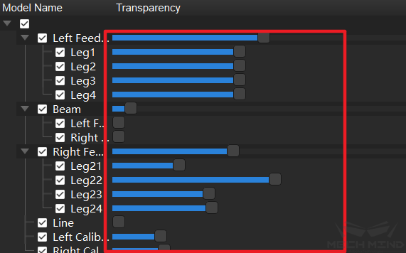
Transparency setting:
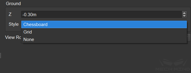
Ground settings:
View rotation method:
The view rotation method can be set as natural perspective or free perspective. Under both methods, the perspective can be adjusted by holding the left mouse button and dragging, and the line of sight is always towards the origin of the natural coordinate system, but with free perspective, the simulation can be rotated with the line of sight that passes the origin of the natural coordinate system as the axis.