Robot
The main content of the robot tab page is shown in figure 1. The function and usage of each option will be introduced below.
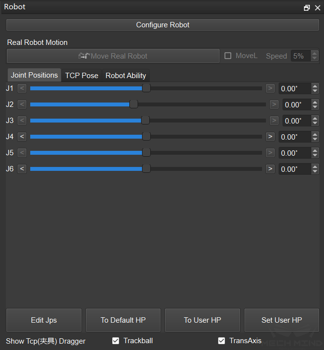
figure 1 Robot tab page
Configure Robot
After clicking Configure Robot, you can import the robot model by selecting the vendor and model of the robot, as shown in figure 2.
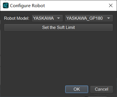
figure 2 Configure robot
Through Set Soft Limit, you can set the soft limit for each axis of the robot. When the soft limit range is less than the existing joint angle setting, a pop-up window will prompt and show the affected Skills, ss shown in figure 3.
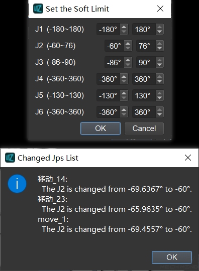
figure 3 Set soft limit
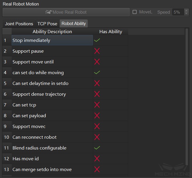
Real Robot Motion
Click Move Real Robot, the real robot will move to the current pose of the simulated robot. On the right side of Mobile Real Robot, you can also check the MoveL option and set its speed if needed.
Joint Positions
Under the joint positions option, the current joint positions data of the simulated robot is displayed. If you need to synchronize with the real robot, please click Sync Robot in the toolbar at the top of the software when the robot is connected. If you need to adjust the pose of the simulated robot, you can drag the slider of each axis or directly enter the value in the right input box, and the simulated robot will move in real time according to the adjustment. Click the Edit Jps button, you can enter the joint angle value of each axis in the pop-up window at one time, as shown in figure 4.
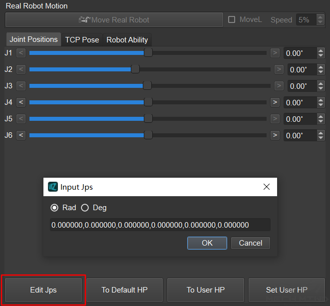
figure 4 Edit joint positions
Click the To Default HP button, and the simulated robot will return to the initial position set in the robot configuration file. Click the To User HP button, and the simulated robot will return to the initial position set by the user. This position is set by the Set User HP button on the right.
TCP Pose
Under the TCP pose option, the current TCP pose data of the simulated robot is displayed. The TCP pose can be adjusted through the following Quaternion and Euler Angles options, or you can directly input the TCP pose through Edit Pose, as shown in figure 5.
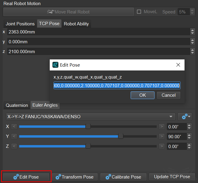
figure 5 Edit pose
Click the Transform Pose button to transform the current pose to a new pose by defining a transformation. As shown in figure 6, you first need to select the reference coordinate system, and then define the transformation through XYZ coordinates, quaternion, Euler angles or Edit Transform button, the simulation robot will display the transformation result in real time. If you need to save the result, please click Apply; if you don’t need to save the result, please click Cancel to exit, and the simulated robot will return to its original position.
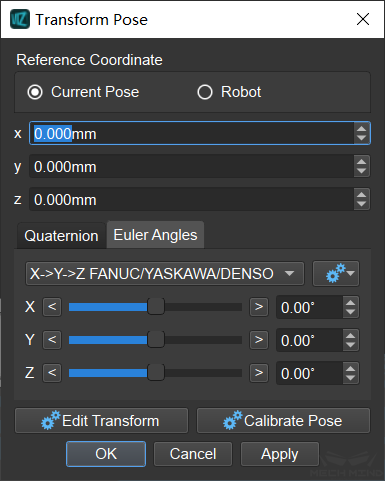
figure 6 Transform pose
If you need to calibrate the TCP pose, please click the Calibrate Pose button, and then follow the pop-up prompts to calibrate, as shown in figure 7.
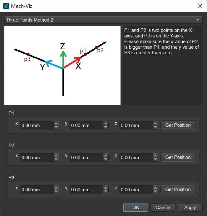
figure 7 Calibrate pose
When the robot is connected, click Update TCP Pose, Mech-Viz will obtain the TCP pose from the real robot.
Show TCP Dragger
This option refers to the dragger of the end effector on the simulated robot. If the Trackball and TransAxis options are checked, you will be able to intuitively adjust the TCP pose by directly dragging the end effector on the simulated robot.