End Effector & Objects
Add End Effector Models
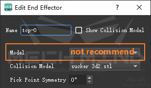
Projects that require point cloud collision detection must load end effector models. It is generally recommended to add only the collision models and not the display models.
Advantages:
The project folder will be smaller, because the storage size of the display model is about 3 times that of the collision model;
Editing will be easier. When the end effector is displaced, the collision model is only to be loaded and set once. If both the display model and the collision model are added, they shall be set separately;
The problem of inconsistency between the display model and the collision model is eliminated, and the situation that the collision detection is not as expected is avoided.
In addition, the collision model shall be as rough as possible, delete the details, and keep the contours required for collision detection only, otherwise it will affect the software calculation speed.
Collision Models of .binvox Format
For some scenario that needs high accuracy of point cloud collision checking, it is recommended to add model with .binvox format.
Save the model in the format of .stl or .wrl by using the CAD software like SolidWorks.
The .binvox model generated from .stl model is only a frame.
The .binvox model generated from .wrl model is a solid model.
The degree of collision can be shown more specific if using solid model, such as touch or real collision, however, it also cost more time to calculate.
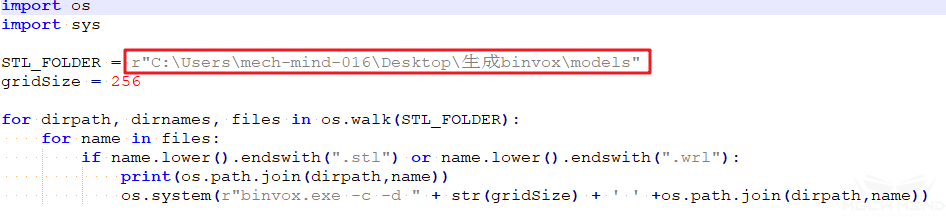
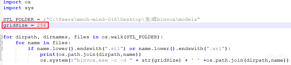
Download “generate_binvox.zip” and unzip it, open “generate_binvoxes.py” with notepad++, change the file path of the .stl or .wrl model as follows(do not delete “r”), double click to run it after saving.
After execution, the models in format .stl or .wrl are converted to the .binvox file.
Attention
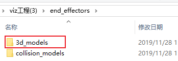
Only the model generated by ascii format can be converted , it is not support binary format. If the .stl model is in binary, you can add it from 3D Models tab in Mech-Viz, after saving, you can find the ascii-generated model in the path “end_effectors/3d_models”, as the figure below:
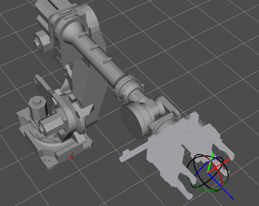
The loaded .binvox model in Mech-Viz:
The roughness of the .binvox model is affected by the value of gridSize:
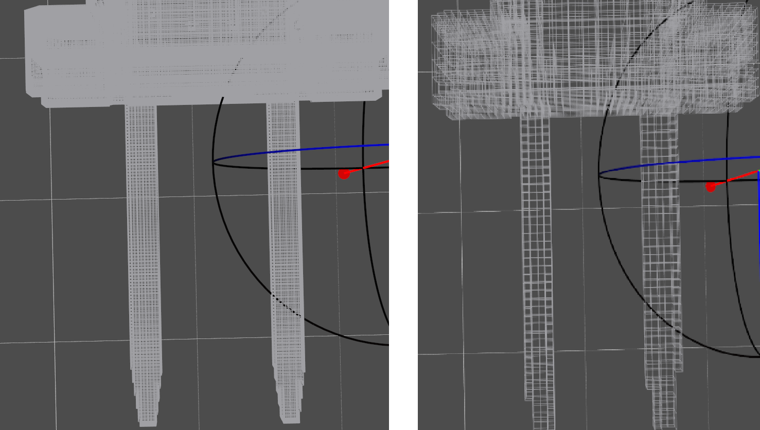
gridSize = 512 & gridSize = 100
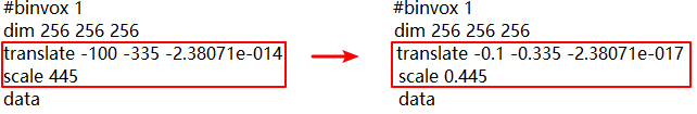
If the loaded model in the scene is unexpected huge, that is because the unit is not proper. Open the .binvox model file by notepad++, reduce the values of scale and translate 1000 times, then load the model again.
Configuration of Objects to Pick (for Move Planning)
Each object to be picked has an Object Pose (Obj Pose) , and the software will calculate the corresponding TCP pose and control the robot to pick it.
Symmetry and Picking Relaxation
- Symmetry:
The objects to be picked or the pick points are often symmetrical. Please visit Symmetry for more information.
- Picking Relaxation:
Due to the adaptability of the end effector (especially the sucker) or the object itself, a certain deviation between the end effector and the object can be allowed when picking. By setting the picking relaxation, the robot can actively use such “tolerable deviations” to avoid problems such as collisions and singularities. In principle, the picking relaxation is “tolerable deviation” based on the pick point. In order to obtain the optimal motion trajectory, the software will consider the symmetry of the pick point, the picking relaxation and the symmetry of the object together during the picking process; and the object pose will be selected according to the symmetry of the object when placing.
Attention
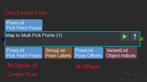
The distinction between the symmetry of the pick point and the picking relaxation directly depends on the output of the Mech-Vision project. Only when the Mech-Vision project uses Map to Multi Pick Points, the final effects of them are different. For Mech-Vision projects that only output poses, the picking relaxation is equivalent to the symmetry of the pick point.
Clarification on Symmetry and Picking Relaxation
Pick Point Symmetry
The symmetry of the pick point is related to the way the end effector picks the object, and is used to select the optimal picking pose. The figure below shows how to set the symmetry of pick point:
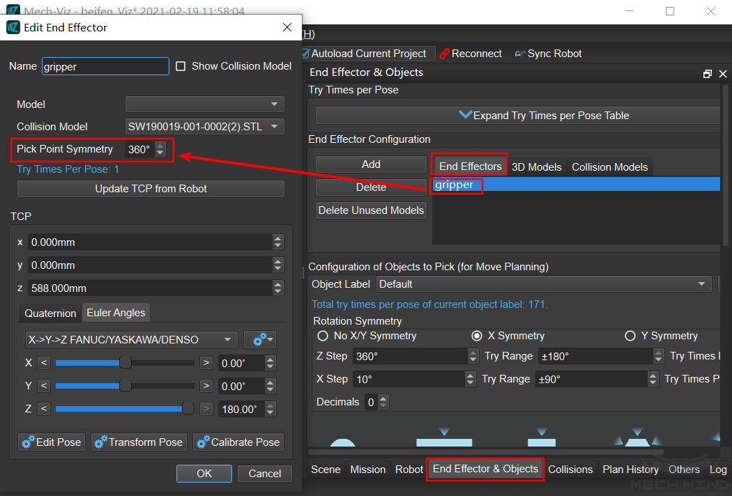
Please visit Symmetry of Pick Point for more information.
Object Symmetry and Picking Relaxation
Object Label : When the visual point obtained from visual_move has a label, it will be searched here, and the symmetry settings of this type of object will be applied. When no matching label is found, the symmetry settings corresponding to the “Default” label will be applied. The “Default” label cannot be deleted, but user can add or delete other labels.
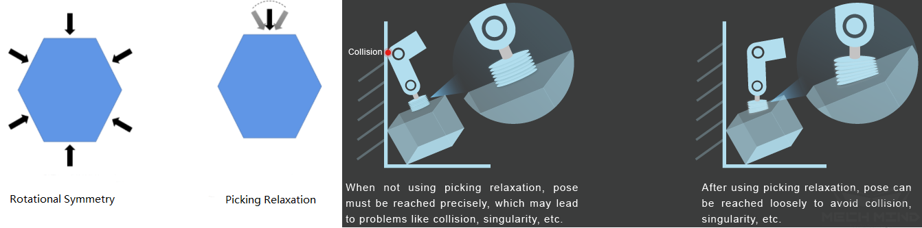
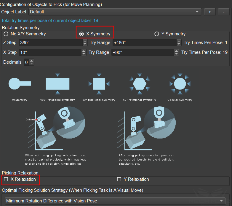
Rotation Symmetry : In the X-axis symmetry and Y-axis symmetry of the object, only one of the two is supported (the Z-axis is not affected by this). This is because if an object has both X-axis and Y-axis symmetry, the object is generally a sphere, and this is usually not the case in practice. If user needs to set symmetry for a spherical object, please try to set it by picking relaxation instead of symmetry.
Picking Relaxation : The picking relaxation supports the setting of X-axis relaxation and Y-axis relaxation at the same time, but it is applied separately during application. That is, the reference pose rotates around the X axis or the Y axis, instead of rotating around both axes at the same time, and there is a mutually exclusive relationship between the picking relaxation and the symmetry of the object. For example, X-axis relaxation cannot be selected if the X-axis symmetry is selected. As the figure below shows.
The Difference between X/Y Axis Symmetry of Object and Picking Relaxation
The application scenario of X/Y axis symmetry of object is that the relative position relationship between the end effector and the object on this axis is not allowed to change. Usually, X/Y axis symmetry is used when there are requirements for the placing pose of the object. For example, for crankshaft picking, the X-axis rotation angle of the crankshaft when it is finally placed is very important in many scenarios. At this time, it is necessary to set the X-axis symmetry so that the crankshaft can be placed exactly at the required angle.
The application scenario of the picking relaxation is that the relative positional relationship between the end effector and the object on the axis is allowed to change. For example, when using a sucker to pick object, even if there is a small angle deviation between the sucker and the object, but due to the flexibility of the sucker, the object can still be successfully picked, as shown in the following figure:
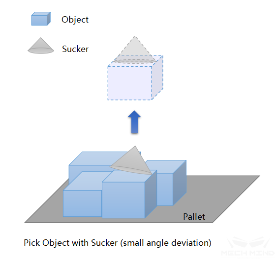
The same is true for end effectors and workpieces. For scenes such as picking crankshafts, chain rail joints, etc., the object can still be picked if a small angular deviation is allowed in a certain axis direction of the object,.
The planning time may be too long when the setting is not appropriate
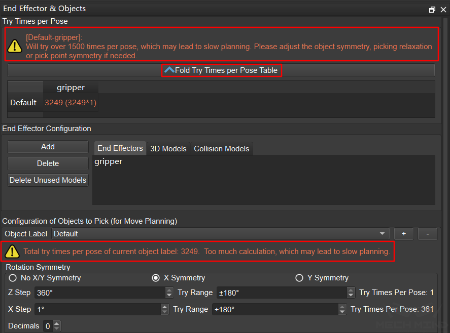
When applying the symmetry of the pick point, the symmetry of the object, and the picking relaxation at the same time, since the number of attempts is the product of the respective number of values of these three items, improper settings may result in too many attempts and the planning time may be too long. Mech-Viz may even crash. Therefore, the software will give a warning when the number of attempts exceeds 1500. The warning can be viewed in detail by clicking Expand Try Times per Pose Table, as shown in the figure below:
Optimal Picking Solution Strategy (When Picking Task Is A Visual Move)
There are currently three modes: Default, Minimum Global Rotation, and Minimum Rotation Difference with Vision Pose.
For compatibility with functions that may be developed in the future, the “Default” mode is introduced. For the current version, “Default” is equivalent to “Minimum Global Rotation”.
Minimum Global Rotation: When this mode is selected, symmetry will be applied according to the principle of the minimum Z-axis rotation of the pick points in the whole process of “pick-place”. The advantage of this mode is that it can avoid the robot from turning meaninglessly after picking the object, and avoiding the risk of the picked object falling.
Minimum Rotation Difference with Vision Pose: this mode is introduced because in some special application scenarios, the rotation during the picking and placing process does not matter, and the end effector needs to be visually guided to rotate to achieve the goal. For example, the end effector of a certain project is shown in the figure below. The object is a cylinder and is symmetric at any angle. Therefore, the end effector can pick the object at any Z-axis angle as long as it does not cause interference. When picking objects close to the wall of the box in a deep box, if “Minimum Global Rotation” is applied, the picking pose may be that the end effector is close to the box wall for picking, which is high risky. At this time, the Z-axis angle of picking pose can be guided by vision, such as editing the Mech-Vision project so that the X-axis of the object poses all point to the center of the box. In this way, when planning the picking pose, keeping the rotation difference with the visual pose to a minimum can guide the end effector to be as far away as possible from the box wall when picking, and improve the safety of picking. This Mech-Vision project gives two kinds of labels, which represent the center and the inner wall of the box respectively. Edit these two types of labels separately in Mech-Viz. Apply “Minimum Global Rotation” to the objects in the center of the box to avoid unnecessary rotation as much as possible; Apply “Minimum Rotation Difference with Vision Pose” to the objects around inner wall of the box, and Mech-Vision guides Mech-Viz to select a safer picking pose.
Object Size to Pick (When Picking Task Is Not A Visual Move)
It has nothing to do with the object label. It is a global parameter. It is used to give a size to the picked object when picking task is not a visual move. Generally used for testing by developers.