Collision Model Configuration
Collision models in Mech-Viz include robot links, scene objects, end effector, point cloud, detected objects, picked objects and placed objects. Each collision model type is different so the calculation and method of detection will also be different. For the distinction of collision model types, please refer to Collision Model Type .
The configuration methods of each collision model are different, the specific configuration method of each model is as follows :
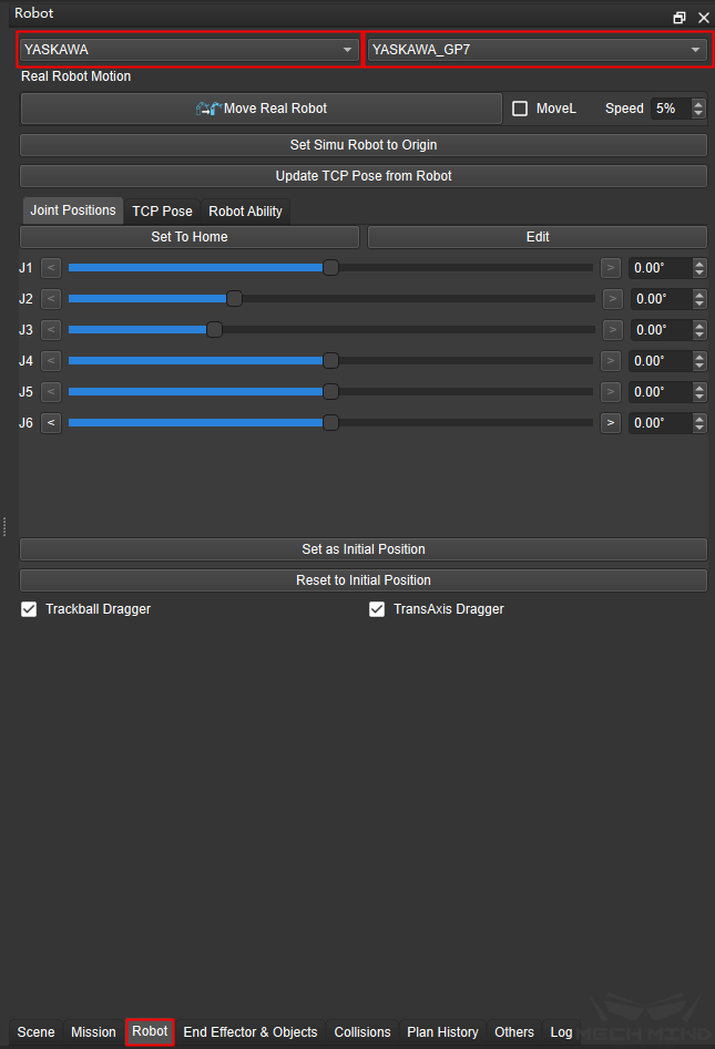
Robot Links: Select Robot at the buttom on the right, then select the brand of the robot and the corresponding robot model, as shown in the figure below.

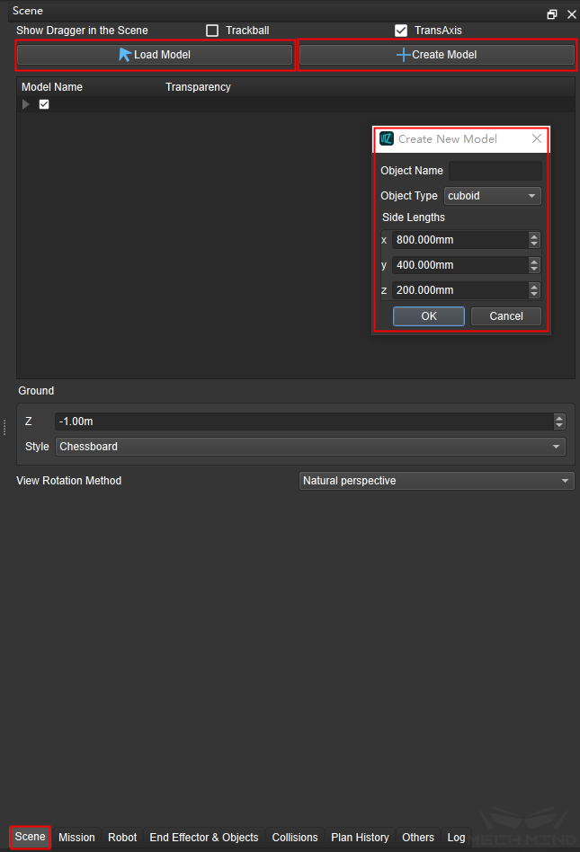
Scene Objects: Select Scene at the buttom on the right, then click Create Model to create cuboid or box (selectd by object type) , you can also click Load Model to load the existing scene object model (support stl, obj, dae and other foramts), as shown in the figure below.

Attention
The model imported by loading needs to be checked the Need Collision Detection in the additional parameter before it can be actually added to the collision detection, ortherwise it can only be displayed as a 3D model.
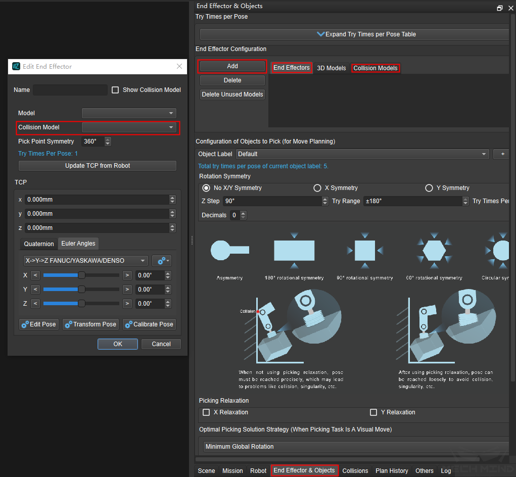
End Effector: Select End Effector & Objects at the buttom on the right, then select the collision model and click Add on the left to select the tool that needs to be added. At this time, the collision model does not actually take effect, you need to select the collision model in the end effector, as shown the figure below.

Tip
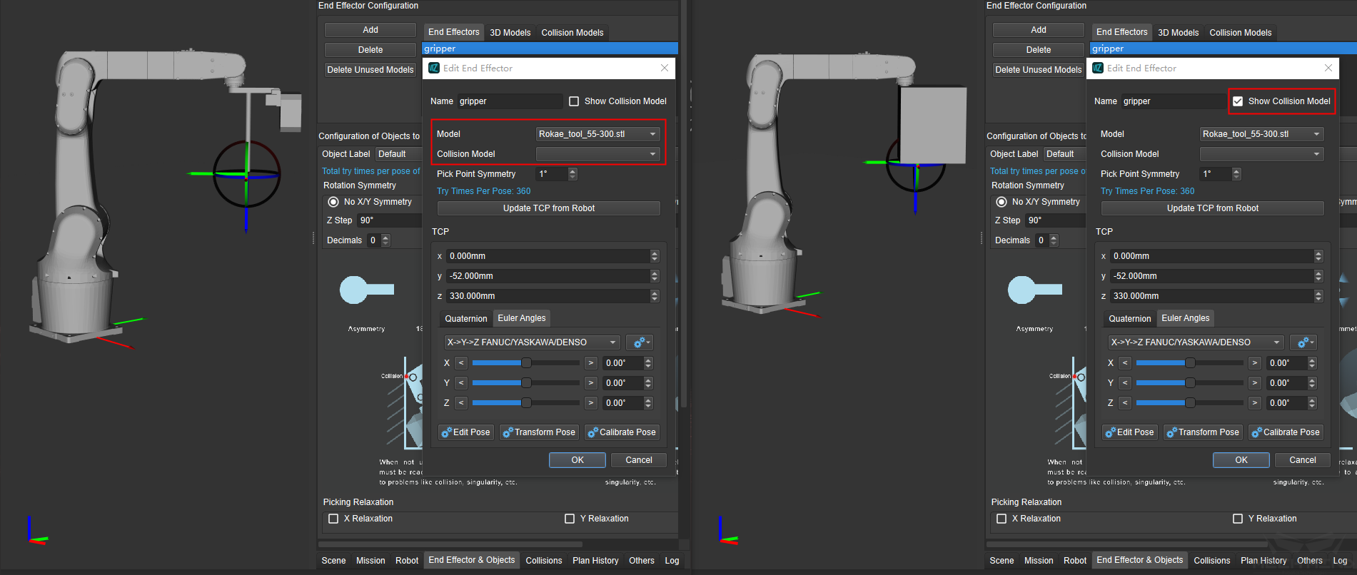
If only the 3D model is available, the bounding box (basic geometry type) can be used as a collision model for the collision detection. You just need to click Show Collision Model after importing the 3D model in the end effector, as shown in the figure below.

Point Cloud: The point cloud model are mostly the detected objects in the process, it need to be imported through the step Send Point Cloud to External Service in Mech-Vision.
Detected Objects: This kind of model need to add the stl model and binvox model of the objects to the collision_models folder in the project, and then use the step Send Point Cloud to External Service through Mech-Vision to send objects information (including pose, label and point cloud etc.) to Mech-Viz by checking Send Object Information as Ture in the parameter settings. For more information about the conversion of the binvox model, please refer to Collision Models of .binvox Format .

Picked Objects: This kind of model is mainly divided into two categories: cuboid and non-cuboid. The configuration method of the non-cuboid model is the same as the detected objects model, the cuboid model need to use the step “From NumberList to Size3DList” to calculate the object size and then send the result to Mech-Viz through the step Procedure Out, after receiving the result Mech-Viz will generate the corresponding collision model, as shown in the figure below.

Placed Objects: This kind of model does not need to be configured in most cases. The placed object model is configured by using the picked object model or the detected object model. The collision detection of this kind of model belong to scene collision.