Small Non-Planar Workpiece Loading
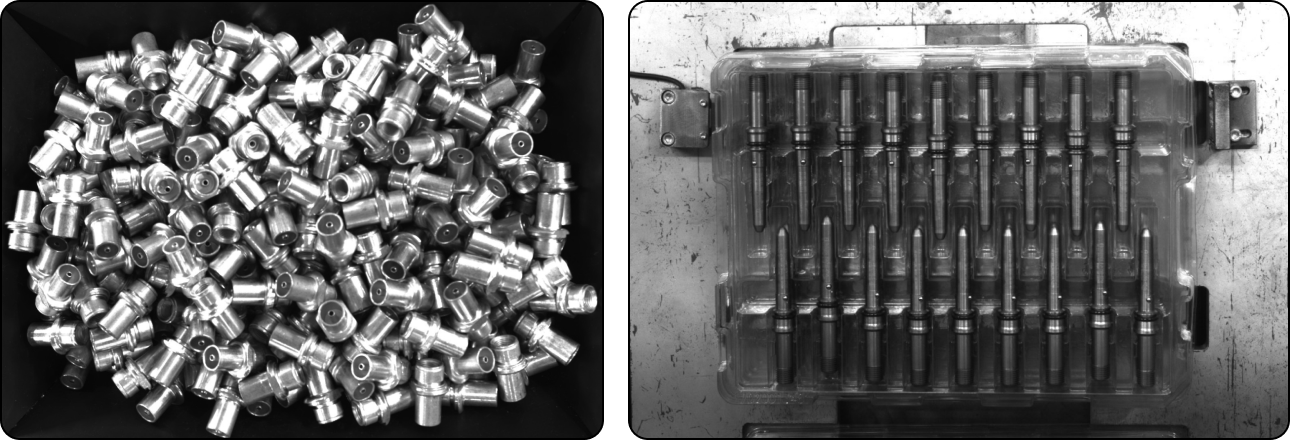
The image above shows the result of small non-planar workpiece loading. For this scenario, the number of the workpieces to be processed is large and their size is small. In this project, deep learning algorithms and 3D matching algorithms are used to recognize the small non-planar workpieces.
Create a New Typical Application Project
Create a Project
Click on in the Menu Bar or New Typical Application Project in the Toolbar to open the following window.
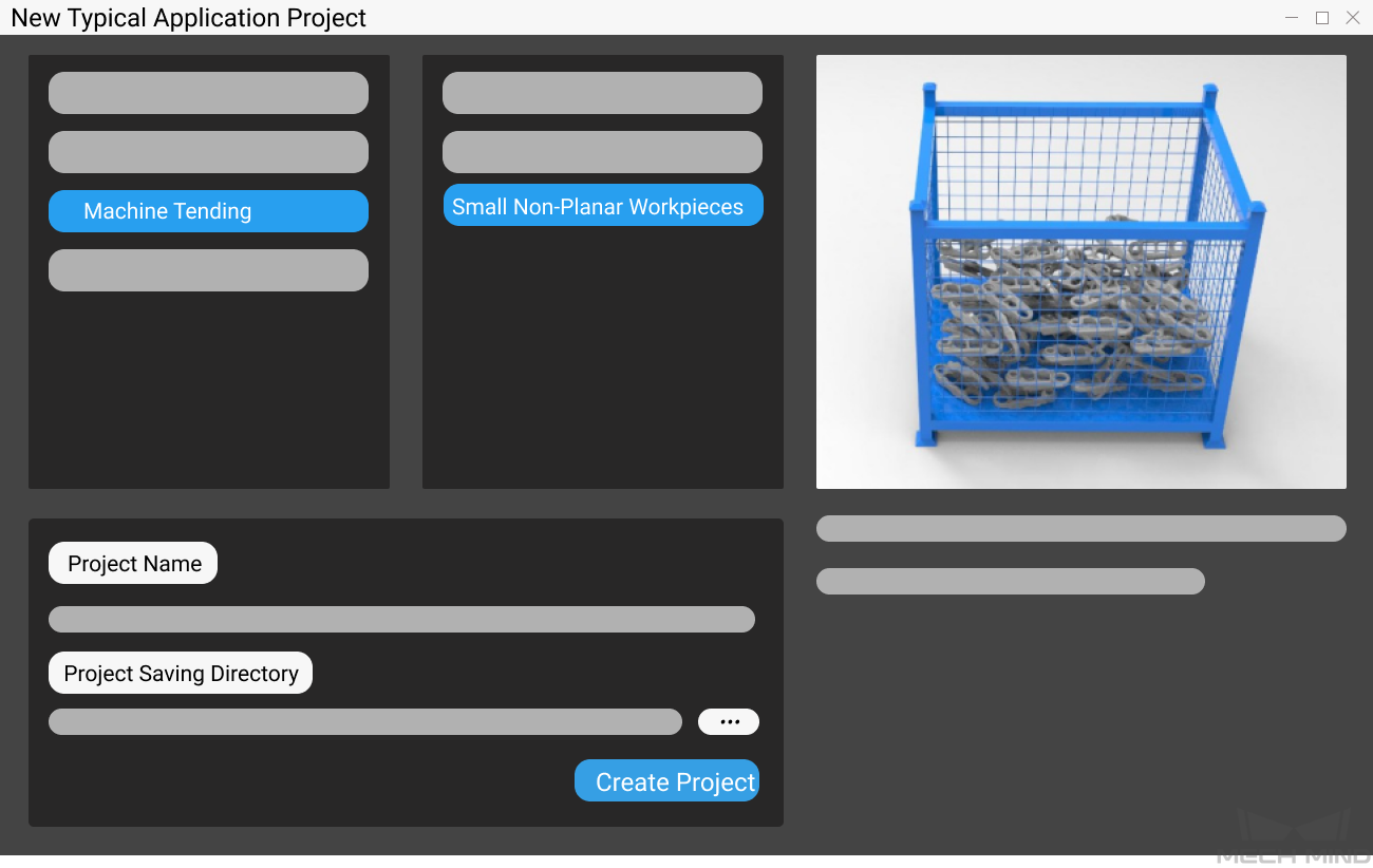
Select Small Non-Planar Workpieces.
Name the project.
Click on
 to select a folder to save the project (it is recommended to create an empty folder), then click Create Project .
Preparation
Before deploying the project, please complete the following preparation:
1. Calibrate the Camera
Calibrating the camera is to obtain the parameter file of the camera, which is used to determine the spatial relationship between the robot and camera.
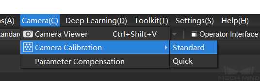
Click on Camera Calibration(Standard) in the Toolbar to calibrate the camera.

Alternatively, you can click on in the Menu Bar to open the same window.
For more information about camera calibration, please refer to Start Calibration - Standard Mode.
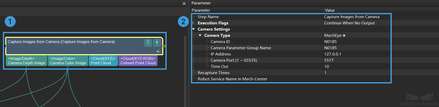
2. Configure the Camera
Before using the camera to capture images, you need to set the type, parameter group name, IP address and other parameters of the camera. For detailed instructions, please see Capture Images from Camera.
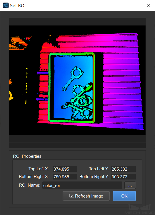
3. Set 2D and 3D ROI
Double click on the Procedure Point Cloud Pre-Processing to display the detailed structure, and set 2D ROI and 3D ROI in the Step From Depth Map to Point Cloud and Extract 3D Points in 3D ROI respectively.
Setting a 2D ROI can increase the deep learning pre-processing speed. Please refer to Instructions for Setting 2D ROI for detailed instructions on setting 2D ROI.
Attention
The way to set a 2D ROI in Step From Depth Map to Point Cloud of the Procedure Point Cloud Pre-Processing is the same as above.
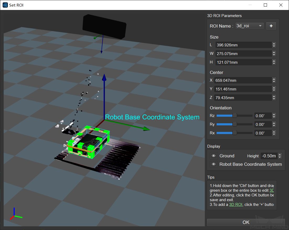
Setting a 3D ROI can extract the point cloud of the target objects and filtered the unwanted points in the backgroung. Please refer to Instructions for Setting 3D ROI for detailed instructions on setting 3D ROI.
Tip
Usually, the small non-planar workpieces are piled randomly in a bin. Setting a 3D ROI is not able to facilitate the algorithms to distinguish the bin from workpieces, and the points in the background cannot be filtered effectively. In these circumstances, Set Static Background for Project may improve the performance of filtering unwanted points.
1. Instance Segmentation
Note
If you already have a super model, you can skip this step and start configuring the deep learning model file.
Instance segmentation is used for detecting and locating each distinct target object in an image, as shown below.
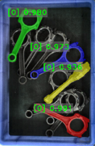
Please see Instance Segmentation for detailed information about training a deep learning model.
5. Generate a Model Point Cloud
Please use the tool Matching Model and Pick Point Editor to generate a model point cloud of the target object, and therefore Mech-Vision can compare the point cloud of the target object to the model point cloud and then generate an actual picking pose.
The model point cloud and pick point generated using the Matching Model and Pick Point Editor are shown below.
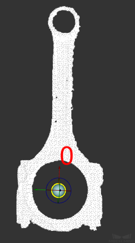
The generated model file will be saved in the project folder.
Project Deployment
During project deployment phase, you will need to set relevant parameters of Steps, and add the configuration files obtained in the preparation phase to corresponding Steps before actually running the project.
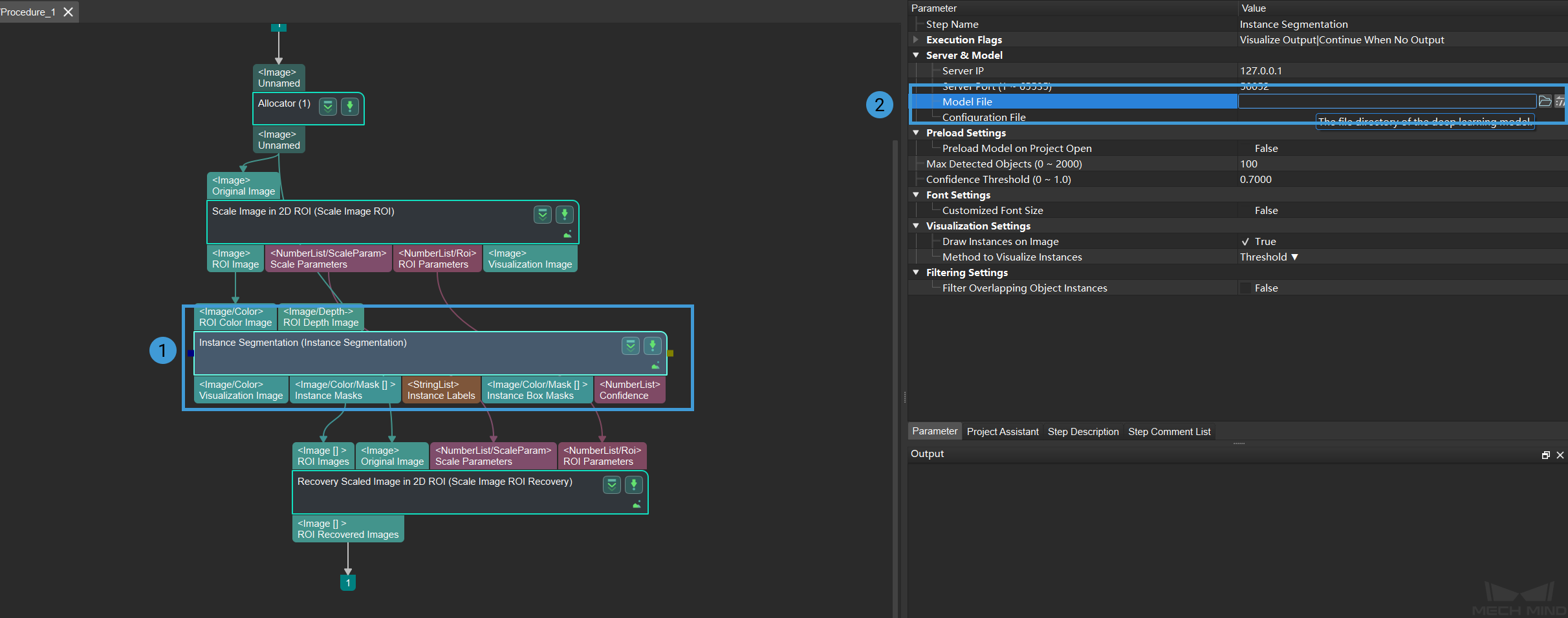
1. Set the DL Model File and Configuration File
Double-click on the Procedure Instance Segmentation to display the detailed structure.
Select the Step Instance Segmentation and click on
 to set the model file and configuration file in the Parameter, as shown below.
2. Set the Model File and Geometric Center File
Double-click on the Procedure 3D Matching to display the detailed structure.
Select the Step 3D Coarse Matching and click on
to set the model file and geometric center file in the Parameter, as shown below.
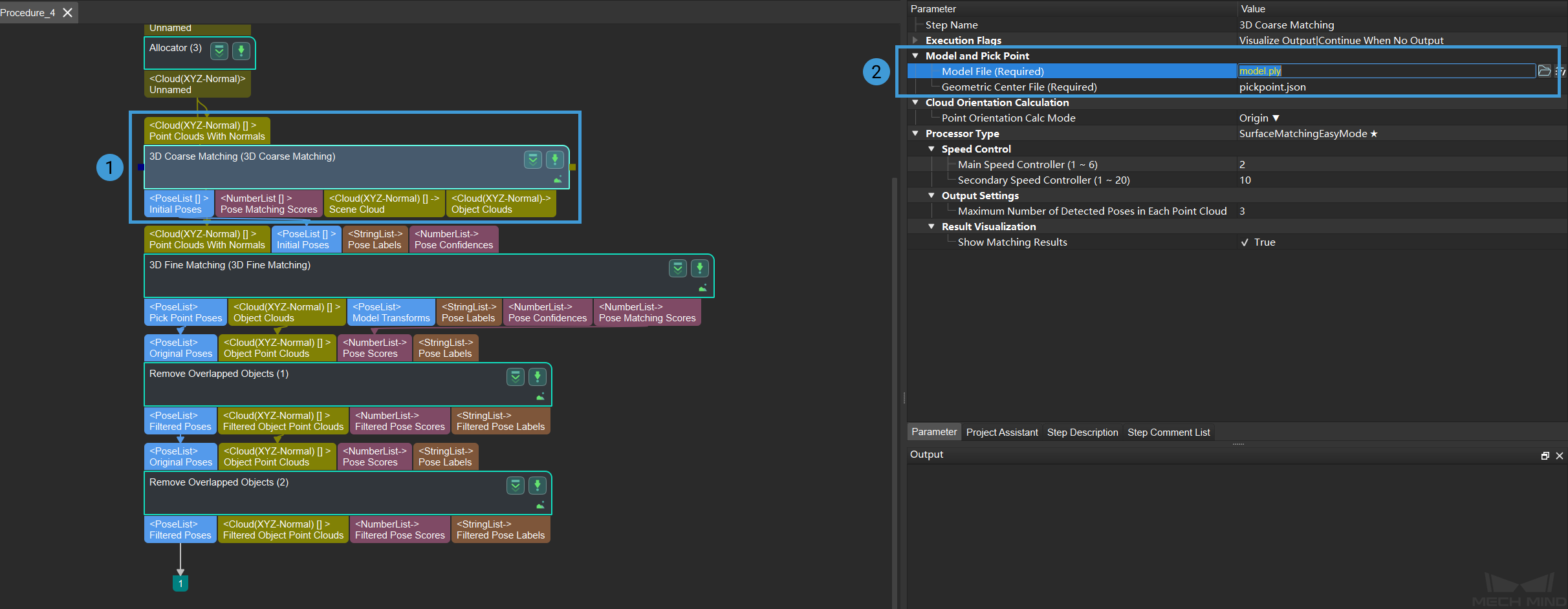
The way to set model file and geometric center file in 3D Fine Matching is the same as it is in 3D Coarse Matching.
Click to see the example of each file
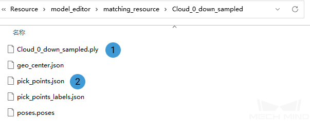
① is a point cloud model file, and ② is a geometric center file.
3. Set Poses Files
Select the Step Map to Multi Pick Points and click on
to set the poses files and important lables in Parameter, as shown below.
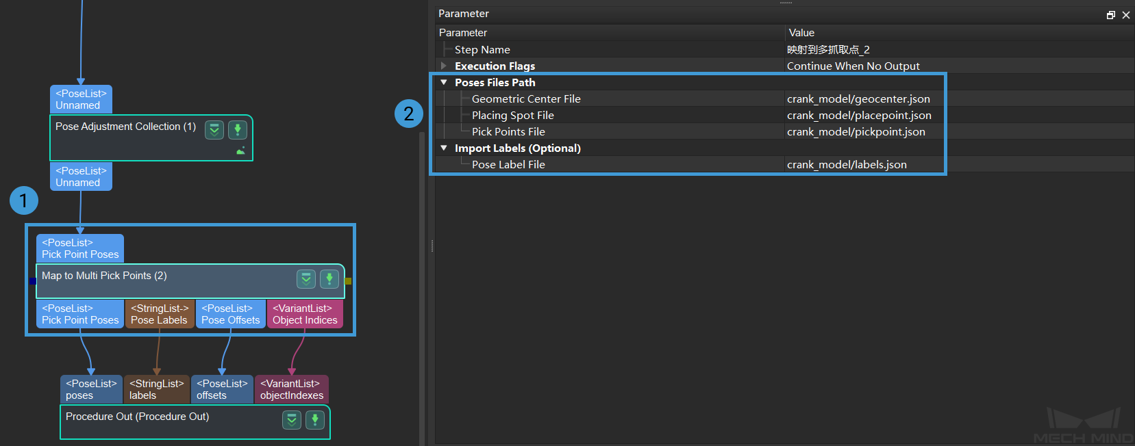
Click to see the example of each file
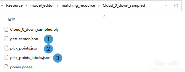
① is a geometric center file, ② is a placing spot file, and ③ is a pose label file.
Running and Debugging
After completing the project deployment, click on ![]() to run the project.
to run the project.
Please see Run the Project and Debug for how to run and debug the project.
Please see Small Non-Planar Workpiece Loading to learn about the algorithms and parameter adjustment of the project.
Tip
If you need to save the images or parameters when debugging the project or before training a deep learning model, you can use the tool Data Storage.
After successfully running and debugging the project, if you need to save the on-site data for future reference or you find that certain part of the project is not performing well and would like to optimize the Step or tune the parameters in an off-site situation, the tools Data Storage and Data Playback can be very useful.
Prerequisites for using the tool Data Playback:
A project file in which the project can run correctly without errors.
On-site source data which is gathered during the whole period while running the project, including 2D color images, depth maps, camera parameter file. Please refer to Data Storage for instructions on how to save the data.