Capture Images from Camera
Function
Obtain color images, depth maps, and point clouds from a real or virtual camera.
Sample Scenario
Usually used as the initial input entry of a vision project. This Step collects data through Mech-Eye Industrial 3D Cameras or third-party cameras or acts as a simulated data source from a virtual camera.
Input and Output
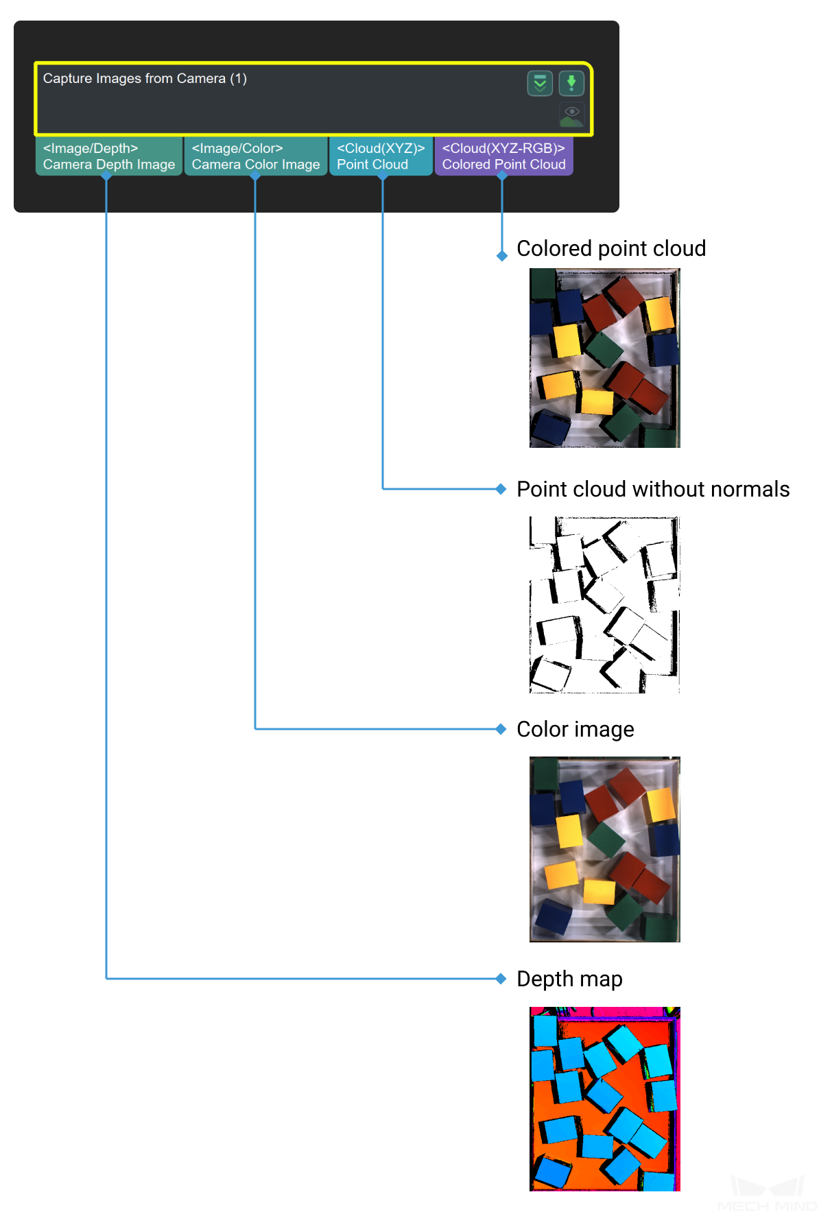
Parameters
Camera Settings
Camera Type
Default Value: MechEyeList of Values: MechEye, VirtualCamera,External2DInstruction: Select MechEye when connecting a real camera, and VirtualCamera when using camera parameter for simulation.Camera ID
Default Value: CAM00000Instruction: Click open an editor to enter the “Camera Connection Assistant” window. Select the camera that needs to be connected and establish a connection. After the connection is successful, click Get Default Camera Parameter to get the intrinisic and extrinsic parameters of the camera (If the camera parameters have been obtained before, there is no need to obtain them again). At the same time, the Mech-Eye interface is activated after the connection is successful, and the user can enter the Mech-Eye Viewer window. If the user need to set up in the Mech-Eye Viewer, please refer to Mech-Eye Viewer.Camera Parameter Group Name
Automatically fill in after the camera number is set.IP Address
Default Value: 5577Instruction: the real IP address of the cameraPort Number
Default Value: 127.0.0.1Instruction: Camera interfaceTimeOut
Default Value: 10sRecommended Value: 10sInstruction: If the camera fails to capture the picture within the set time, it is a timeout. Camera will try to capture the picture again, and 3 consecutive timeouts will cause an exception report.VirtualCamera
Data Path
1. Use the Eye To Hand project for simulation:Instruction: When selecting the image data path, if the image data in the selected path is not stored in the format shown in the following figure, the “Virtual Camera Assistant” will be triggered to assist in the selection of image data: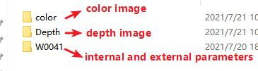 Instructions for adjusting the virtual camera assistant:
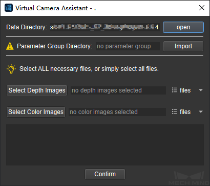 Data Directory: Click open to re-select the file path here. After the correct selection, it will prompt that the setting is completed;Camera ID/Parameter Group: Select the intrinsic and extrinsic parameter files of the camera to be loaded, and click √ to update the parameter group;Select Depth/Select Color Image: Select several color and depth images respectively, and click File ▼ to view the selected image.After all settings are completed, click “OK” and the “Virtual Camera Setting Complete” window will pop up. Then click “OK” to exit.2.Use the Eye In Hand project for simulationInstruction: When selecting the image data path, if the image data in the selected path is not stored in the format shown in the following figure (Compared to the ETH project, the EIH project has one more folder to store the flange poses ), the “Virtual Camera Assistant” will be triggered to assist in the selection of image data:
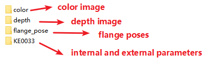 Instructions for adjusting the virtual camera assistant:
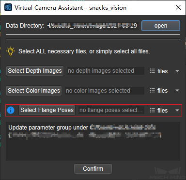 Select Flange Poses: Select the flange poses file to be added, click file ▼ to view the selected file.
Play Mode
Default Value: normalList of values: normal, repeat one, repeat all, ShuffleInstruction: change the mode of reading the image in the fileImage Name Type
Default Value: Complete routeList of values: Complete path, File Name, Base nameInstruction: Change the picture name type of the output imageReCapture Times
Default Value: 3Recommended Value: 3Instruction: The number of retakes when the photo failRobot Service Name in Mech-Center
Instruction: When using EyeInHand for extrinsic parameter calibration, select the robots by name if there are multiple robots.