Getting Started
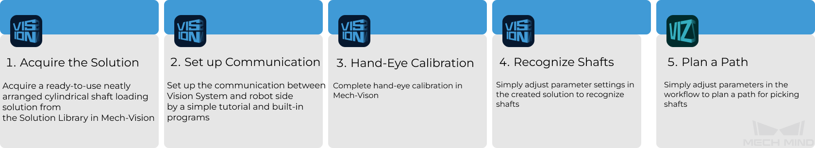
This section will introduce how to easily load the neatly arranged cylindrical shafts from a beginner’s perspective. The overall process is shown in the figure below.
Robot Communication Configuration
Before robot communication configuration, it is necessary to obtain the solution first. Click here to see how to obtain the solution.
-
Run Mech-Vision.
-
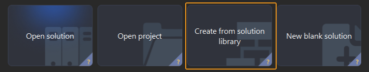
In the Welcome interface of Mech-Vision, click Create from Solution Library to open the Solution Library.
-
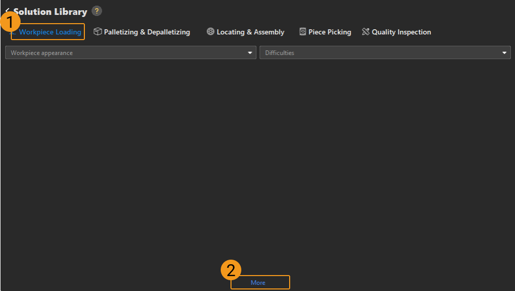
Enter Workpiece loading in the Solution Library, then click on More at the bottom, and click Yes in the pop-up window.
-
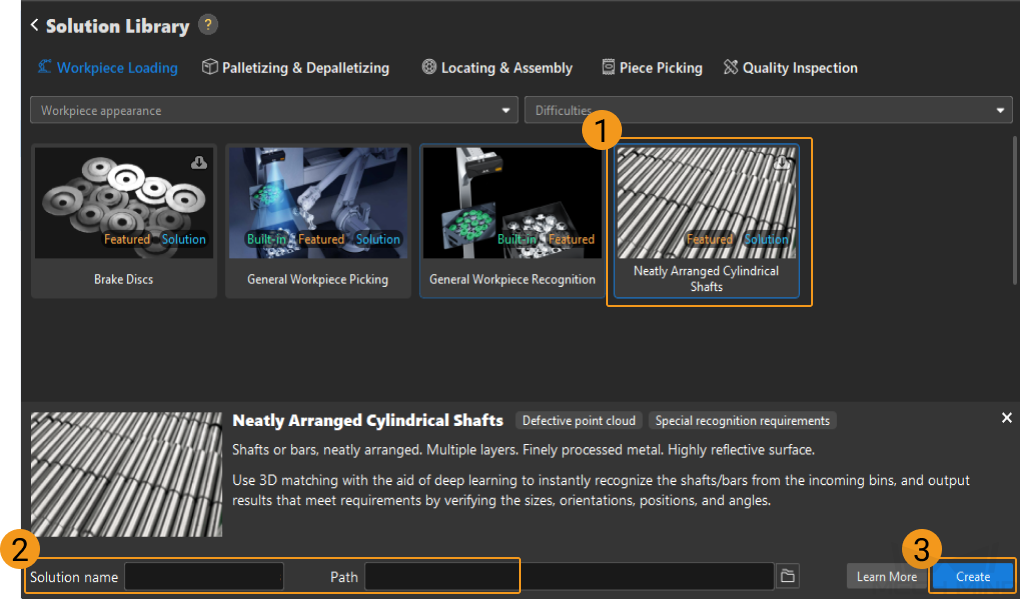
After acquiring the solution resources, select Neatly Arranged Cylindrical Shafts. Then, fill in the Solution name and Path at the bottom, and finally click Create to download the neatly arranged cylindrical shaft loading solution.
Once the solution is downloaded, it will be automatically opened in Mech-Vision.
When deploying a Mech-Mind vision solution, you need to set up the communication between the Mech-Mind Vision System and the robot side (robot, PLC or host computer).
The neatly arranged cylindrical shaft loading solution uses Standard Interface communication. For specific operations, please refer to Standard Interface Communication Configuration.
Hand-Eye Calibration
Hand-eye calibration establishes the transformation relationship between the camera and robot reference frames. With this relationship, the object pose determined by the vision system can be transformed into that in the robot reference frame, which guides the robot to perform its tasks.
Please refer to Hand-Eye Calibration Guide to complete hand-eye calibration.
|
Every time the camera is mounted, or the relative position of the camera and the robot changes after calibration, it is necessary to perform hand-eye calibration again. |
Vision Project Configuration
After completing the communication configuration and hand-eye calibration, you can use Mech-Vision to configure the vision project.
There are two vision projects in this solution:
-
Vis_Shaft_Loading: The main recognition project used to recognize and calculate shaft pick points.
-
Vis_Auto-Generate_Matching_Model: Point cloud model making project used to generate and save shaft point cloud models and pick points.
Generally, you need to run the Vis_Auto-Generate_Matching_Model project first to automatically generate and save the shaft point cloud model. Then configure and run the Vis_Shaft_Loading project to recognize and calculate shaft pick points.
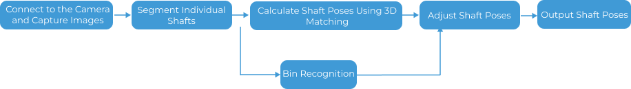
The process of configuring the main recognition project is shown in the figure below.
Connect to the Camera and Capture Images
-
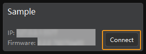
Connect to the camera.
Open Mech-Eye Viewer. Find the camera to be connected and click Connect.
-
Set parameter group.
Click the dropdown arrow next to the Parameter Group on the right-hand side and select the Typical neatly arranged cylindrical shaft loading.
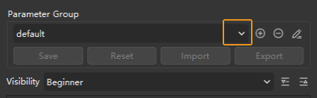
In addition to the default parameter group, Mech-Eye Viewer will also display parameter groups of other typical solutions.
-
Capture images.
After the camera is successfully connected and the parameter group is set, you can start capturing the shaft images. Click the
 button on the top to capture a single image. At this time, you can view the captured 2D image and point cloud of the shaft. Ensure that the 2D image is clear, the shaft point cloud is intact, and the edges are clear. The qualified 2D image and point cloud of the shaft are shown on the left and right in the figure below respectively.
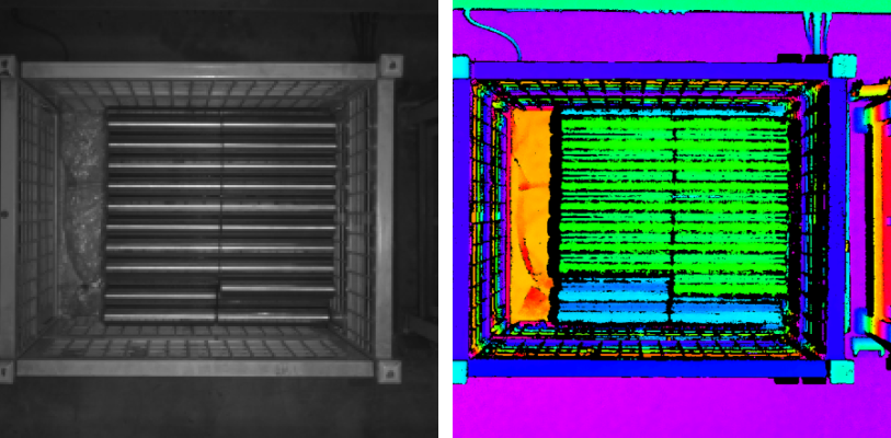
-
Add a camera in Mech-Vision.
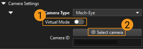
Select the Capture Images from Camera Step, disable the Virtual Mode option, and click Select camera in the Step Parameters panel.
In the pop-up window, click the
 button on the right of the Camera ID.When the button turns into
  , the camera is connected successfully.
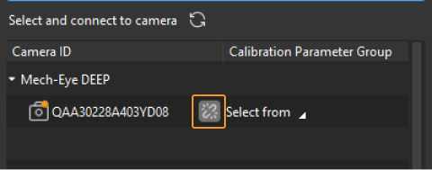
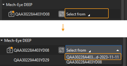
After the camera is connected successfully, you can click Select from and select the corresponding camera calibration parameter group, as shown below.
Once the above settings are complete, you can connect to a real camera. Other parameters can remain at their default values. Click the
 button on the right of the “Capture Images from Camera” Step to run this Step. If no error message occurs, the camera is connected successfully and images can be captured normally.
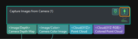
Segment Individual Shafts
-
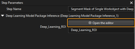
Select the Segment Mask of Single Workobject with Deep Learning Procedure, then click the Open the editor button in Deep Learning ROI in the Step Parameters panel to open the Set ROI window.
-
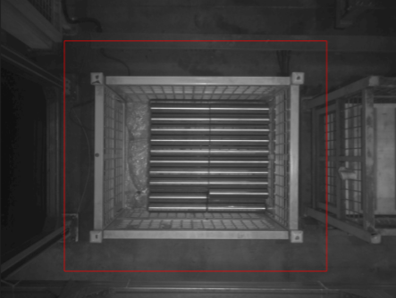
Set 2D ROI in the Set ROI window. The 2D ROI needs to cover the highest-layer shafts, leaving an appropriate margin of about one-third, as shown in the figure below.
Calculate Shaft Poses Using 3D Matching
Set 3D Region of Interest (ROI)
-
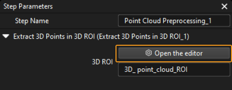
Select the Point Cloud Preprocessing Procedure, then click the Open the editor button in the Step Parameters panel to open the Set 3D ROI window.
-
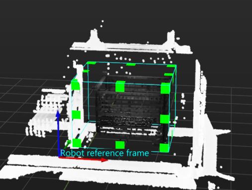
In the Set 3D ROI window, drag the default generated 3D ROI in the point cloud display area to a proper position. Make sure that the green box encompasses the whole bin with a certain margin at the same time, and that the green box does not contain other interfering point clouds, as shown in the following figure.
Create and Select Shaft Point Cloud Model
After downloading the neatly arranged cylindrical shaft loading solution, the shaft point cloud model that can be directly used is selected in the Model Setting parameter in the Locate Workobject by 3D Matching Procedure. If you want to re-create and select the new point cloud model, follow the steps below.
-
Create point cloud model and add the pick point.
Run the Vis_Auto-Generate_Matching_Model project to create the shaft point cloud model and pick point automatically.
-
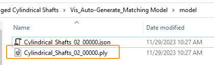
Check the model folder in the Vis_Auto-Generate_Matching_Model project folder.
After running the project, the created shaft point cloud model (PLY file) and pick point (JSON file) will be automatically saved in the model folder.
-
Add the point cloud model and pick point in the Matching Model and Pick Point Editor.
-
Click Matching Model and Pick Point Editor in the Vis_Shaft_Loading project, and click Add model, and then select the point cloud model you have just created.
-
Click the
 button to select the new pick point file, and therefore the pick point can be added to the point cloud model.
-
-
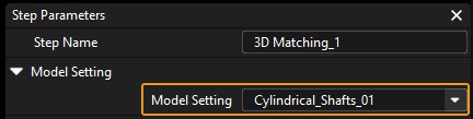
Select the Locate Workobject by 3D Matching Procedure, and select the created shaft point cloud model in the drop-down list of the Model Setting parameter.
Bin Recognition
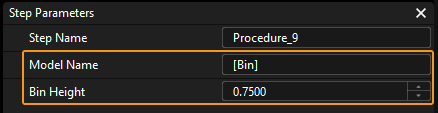
Select the Recognize Bin Procedure, and then enter the actual bin name and height in the Model Name and Bin Height parameters (Unit: m).
Picking
Once the vision project configuration is complete, you can use Mech-Viz to plan a path and then write a robot program for shaft picking.
Path Planning
The process of path planning is shown in the figure below.

|
The Standard Interface communication is used for path planning in the neatly arranged cylindrical shaft loading solution. For more information on the path planning under the Master-Control communication, please download the Viz_Shaft_Picking.zip. |
Configure Scene Objects
Scene objects are introduced to make the scene in the software closer to the real scenario, which facilitates the robot path planning. For specific operations, please refer to Configure Scene Objects.
Configure the Tool
The end tool should be imported and configured so that its model can be displayed in the 3D simulation area and used for collision detection. For specific operations, please refer to Configure the Tool.
Adjust the Workflow
The workflow refers to the robot motion control program created in Mech-Viz in the form of a flowchart. After the scene objects and end tools are configured, you can adjust the workflow.
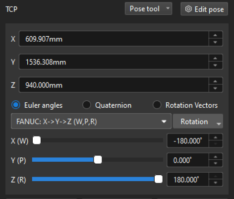
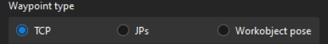
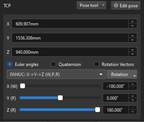
In the introductory stage, you only need to adjust the Above-Bin Fixed Waypoint before Picking and Above-Bin Fixed Waypoint after Picking Steps in the workflow, and there is no need to set parameters for other Steps.

Write a Robot Program
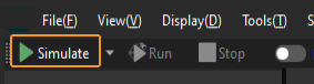
If the simulation results meet expectations, you can write a Standard Interface program.
Please refer to the picking example program and interface commands in Standard Interface communication to learn how to write the robot program.
Now you have learned how to get started with shaft picking.