Add Calibration Points by Multiple Random Board Poses
Using the trajectories generated by the software or the multiple poses added manually, capture images of calibration points at each waypoint on the trajectories in order to construct the correct relationship between the calibration board, camera, and robot.
Calibration Preset
Select a directory to save calibration results
Launch the Mech-Vision software and select Camera \(\rightarrow\) Camera Calibration \(\rightarrow\) Select a directory to save calibration results (if a Mech-Vision project is opened, Use current project directory is chosen by default), as shown in Figure 1.

Figure 1 Select a Directory to Save Calibration Results
Select a calibration setup
Select the corresponding calibration type (select Eye to Hand for this section), as shown in Figure 2.
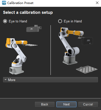
Figure 2 Select the Calibration Type
Check the robot connection status and select the calibration method
If the robot is connected, the window in Figure 3 will be shown. Select Move and capture images automatically using robot and click the Finish button to enter the calibration interface.
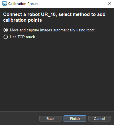
Figure 3 Select the Method to Add Calibration Points
If no robot is connected, select the correct robot type or go back to the previous step and retry after connecting a robot in Mech-Center, as shown in Figure 4.
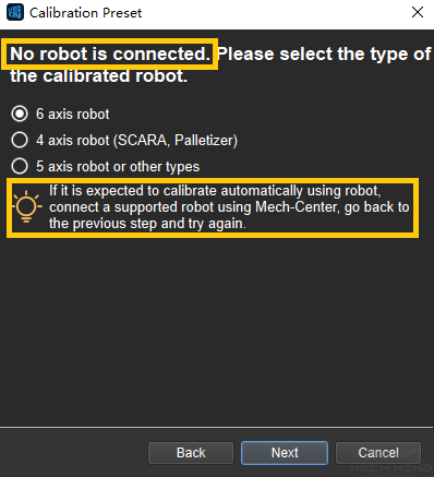
Figure 4 No Robot is Connected
Note
In the following calibration process, a connected 6 axis robot is used as an example. For the details on special types of robots, please refer to Multiple Random Board Poses.
Connect to Camera
Select the camera
When the network is well connected and the camera works normally, the camera ID will automatically appear under the “Detected Cameras & Local Parameter Groups” list. After selecting the camera, click Connect, and the camera will connect to the Mech-Vision software, as shown in Figure 5 below.
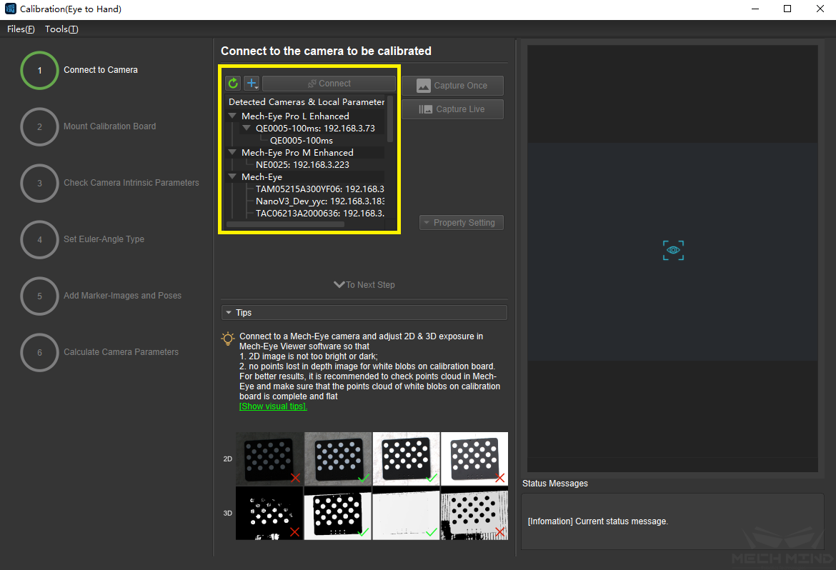
Figure 5 Connect to the Real Camera
Capture images
After connecting to the camera, select Capture Live or Capture Once to view the captured images on the right side of the interface, as shown in Figure 6 below (it is suggested to stop capturing images once the images in the view meet the requirements. Otherwise, multiple refreshes may affect the next calibration step).
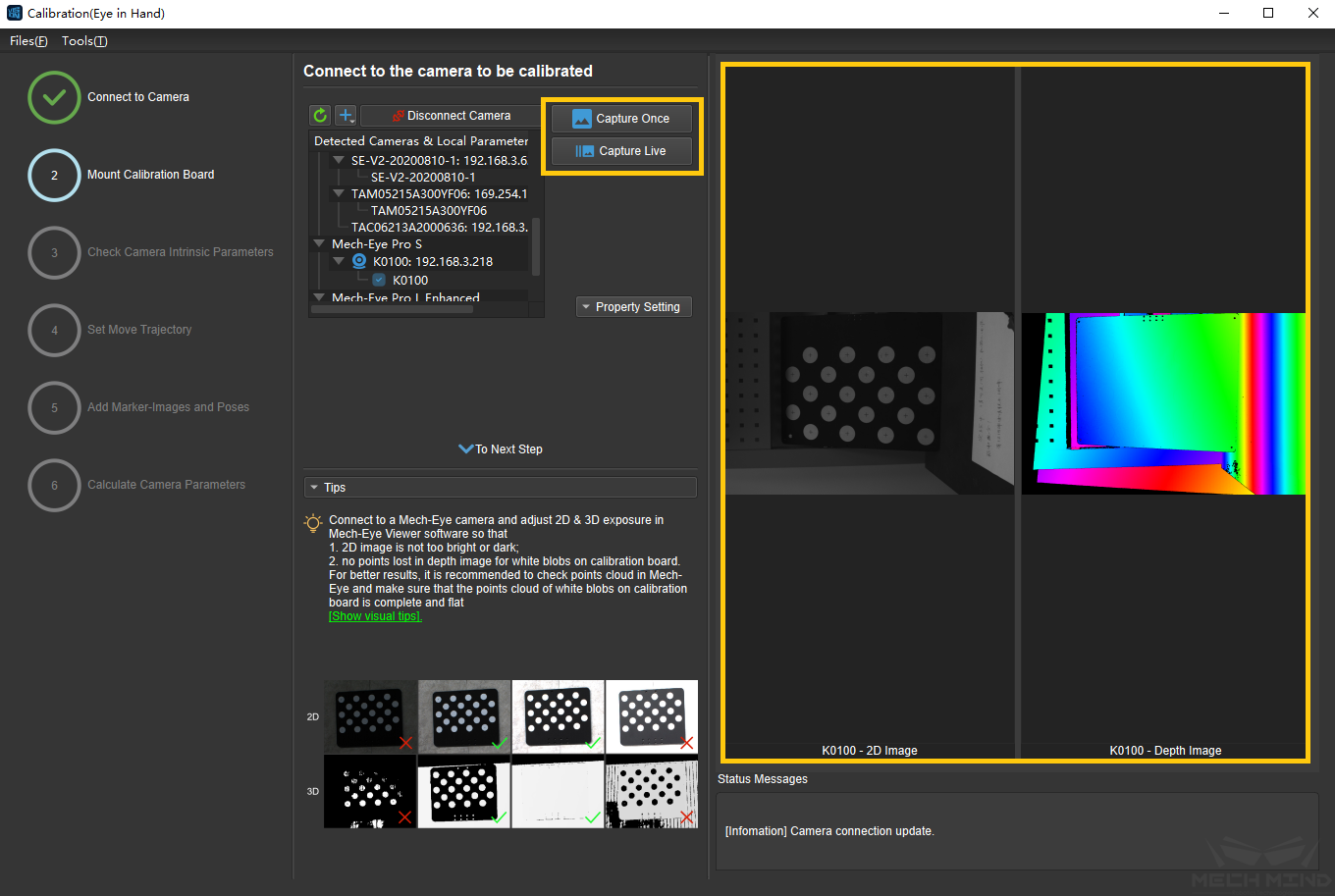
Figure 6 Capture Images
Manually add camera
If the camera is functioning normally but cannot be found under the list of detected cameras, please manually add the camera IP. Click the + icon, and a dialog box will pop up, as shown in Figure 7 below. Fill in the corresponding camera name and camera IP to add the camera to the detected cameras list. Then, connect the camera following the steps mentioned above.
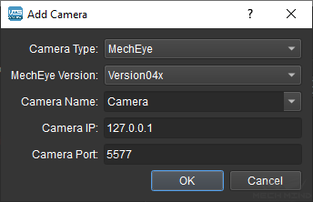
Figure 7 Manually Add Camera
Mount Calibration Board
Select the type of calibration board and put it in the camera’s field of view. The operation interface is shown in Figure 8 below.
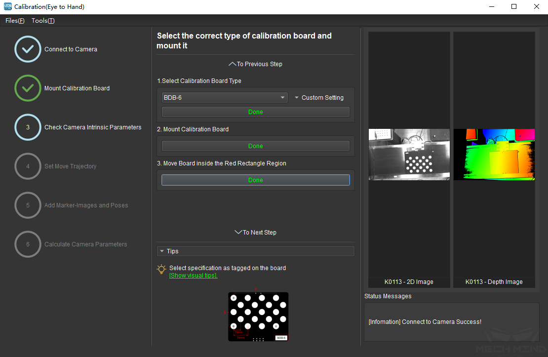
Figure 8 Select and Install the Calibration Board
Specific steps are as follows:
Select the corresponding calibration board model (the model nameplate is affixed on the top of the calibration board), and click the Confirm button.
Confirm that the calibration board is installed on the robot and within the camera’s field of view. Click the Confirm button when finished.
Make sure the calibration board is within the red rectangle in the 2D image, and click the Confirm button.
Check Camera Intrinsic Parameters
Check Camera Intrinsic Parameters
After mounting the calibration board, check if the camera parameters are correct in order to ensure that feature points can be detected during the calibration process. Click the Check Camera Intrinsic Parameters button, and the result of the intrinsic parameter checking will be displayed in a pop-up window. Figure 9 shows a successful intrinsic parameter check.
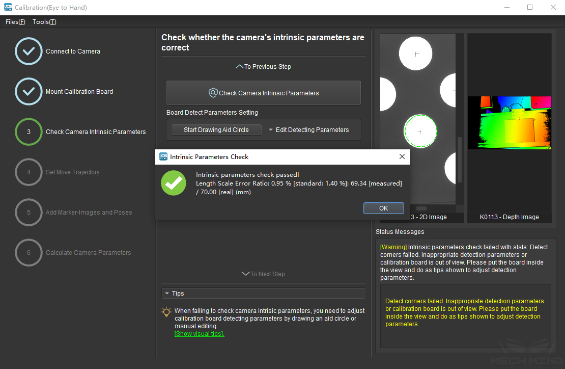
Figure 9 Check Camera Intrinsic Parameters
Generally, when the lighting conditions are good and the camera settings are appropriate, the intrinsic parameter check will pass by simply keeping the default values. Figure 10 shows a successful detection of the feature points.
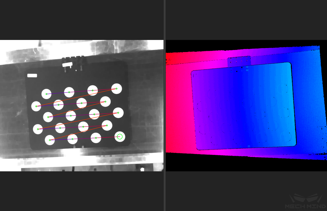
Figure 10 Detected Feature Points
Draw Aid Circle
If the intrinsic parameter check fails, draw an aid circle or manually adjust the calibration board detection parameters. Select the Start Drawing Aid Circle button and draw a circle coinciding with a circle in the calibration board. After which, the detecting parameters of the circles should change.
If the user chooses to manually adjust the detecting parameters, simply click Edit Detecting Parameters and change the values accordingly.
After completing the above steps, click the Check Camera Intrinsic Parameters button again to get a new result. The steps are shown in Figure 11 below.
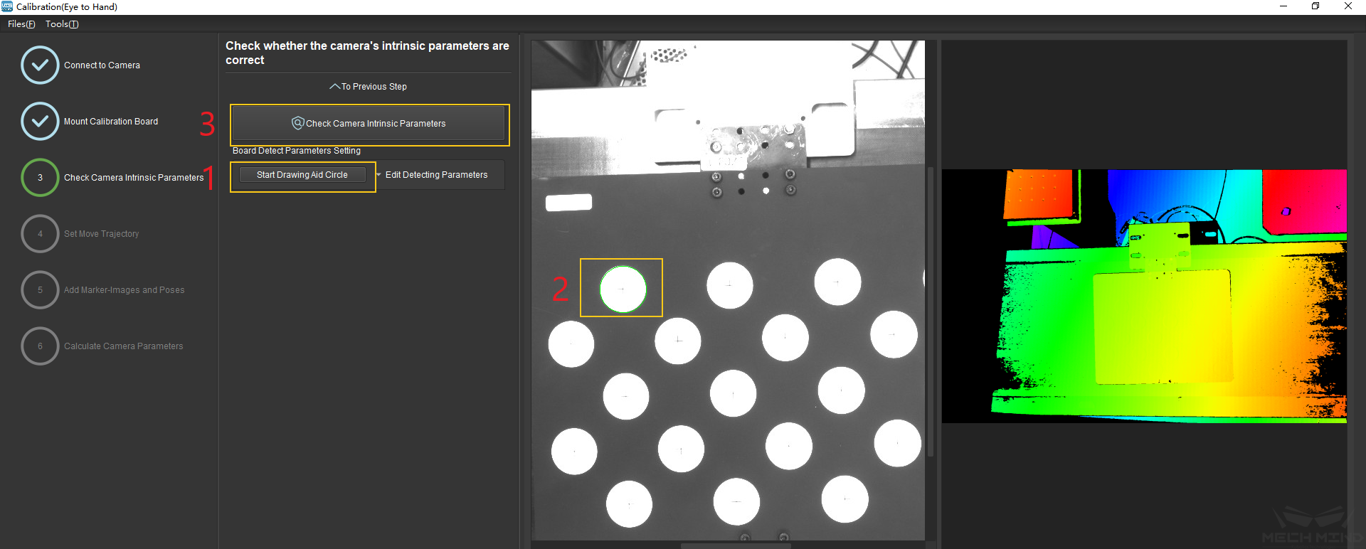
Figure 11 Draw the Aid Circle
Tip
If the calibration circles are too small to be selected easily, the user could right click the 2D image, uncheck Fit to Window, and select Normal Size. Start drawing aid circles after adjusting the size of the image.
If the feature points are still not detected, please adjust the camera settings according to the on-site operating conditions. Detailed information can be found in Mech-Eye Viewer.
Set Move Trajectory
Set Calibration Height Range
The robot trajectory will be automatically generated. In order to ensure that the robot can successfully complete the movement, it is necessary to set a proper height limit according to the size of the robot’s working space. The details are shown in Figure 12.
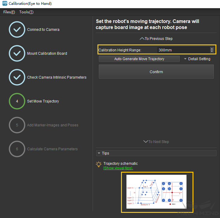
Figure 12 Set the Calibration Height Range
Automatically generate move trajectory
After setting the trajectory range and ensuring that Mech-Viz is connected properly, click the Detail Setting button to set detailed parameters such as height, layer numbers, etc. Then, click the Auto Generate Move Trajectory button, and the program will automatically generate each waypoint of the trajectory. A dialog box will pop up after completion. The steps mentioned above are shown in Figure 13 and Figure 14 below.
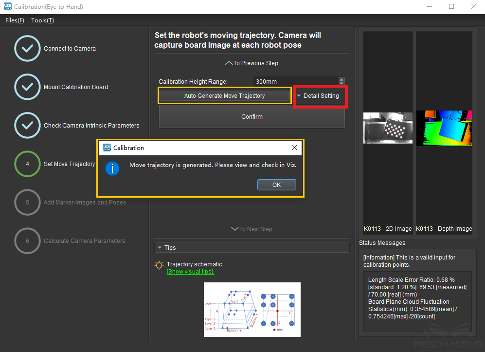
Figure 13 Automatically Generated Trajectory
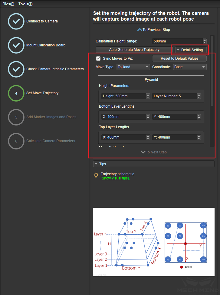
Figure 14 Detail Setting
IMPORTANT!!! Check trajectory in Mech-Viz
In Mech-Viz, click the robot tab. Select the current robot type and click the Sync Robot button. The distribution of the waypoints in the auto-generated trajectory is displayed, as shown in Figure 15. The user must check that the trajectory is reasonable and will not collide with obstacles in the environment!!!
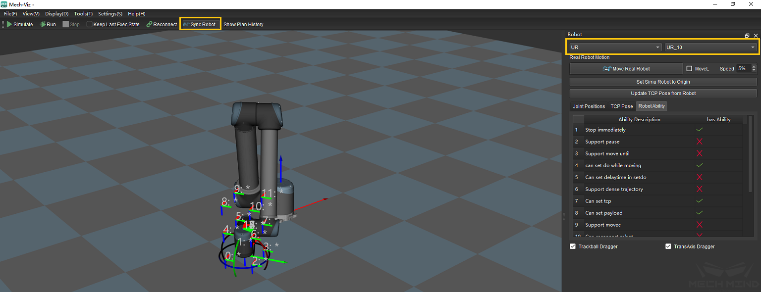
Figure 15 Check the Automatically Generated Trajectory in Mech-Viz
After ensuring that the trajectory is safe, return to Mech-Vision and click the Done and To Next Step buttons, as shown in Figure 16 below.
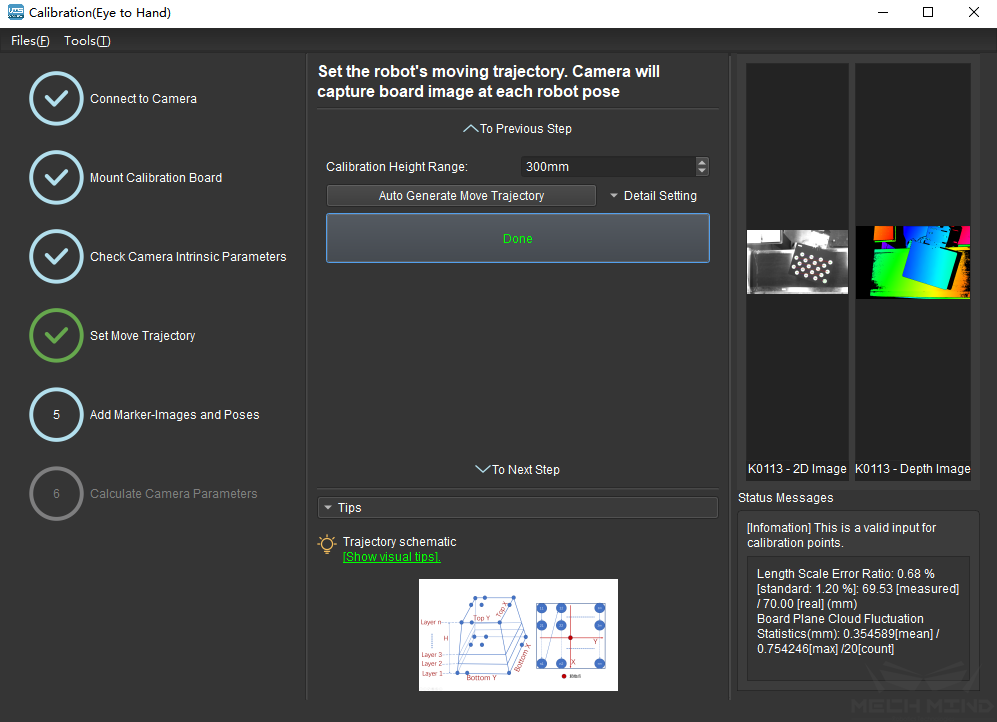
Figure 16 Confirm the Automatically Generated Trajectory
Add Marker-Images and Poses
Preset for calibration
Enter the Add Marker-Images and Poses interface. As shown in Figure 17, check the Save Images option, choose the corresponding robot name, and click the Move Robot along Trajectory and Add Board Images button.
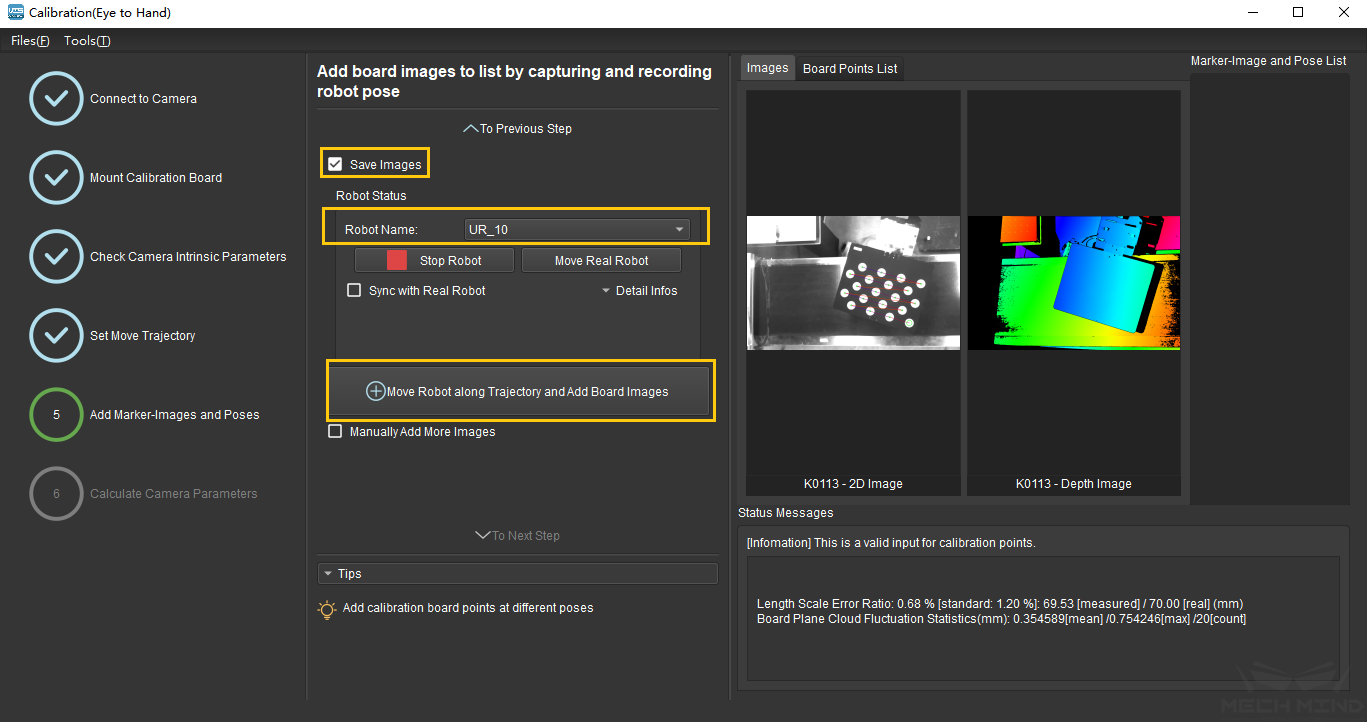
Figure 17 Preset for Calibration
A safety tips will pop up before starting the calibration, as shown in Figure 18. Make sure that the operation environment is safe and then click the OK button.
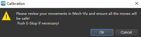
Figure 18 Safety Tips before Starting Calibration
Calibration process
Figure 19 show the interface when the calibration process is running. Please stay away from the robot working area to keep safe. The progress bar will load from 0% to 100% and the captured images can be seen in the right viewer at the same time.
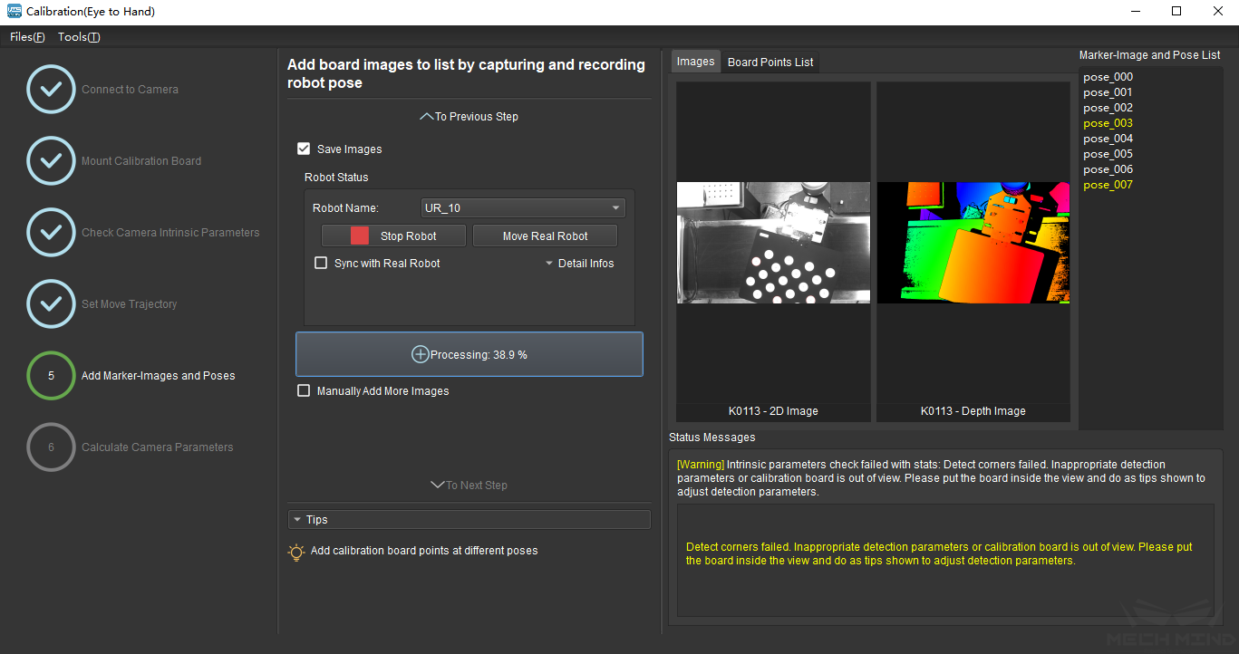
Figure 19 Calibration Process is Running
Attention
Clicking the Stop Robot button can exit the calibration process. But the robot will not stop until it finishes the current waypoint. In case of emergency, please press the emergency stop button on the robot teach pendant to stop the robot immediately.
Detect Deviation of measurements
During the calibration process, a prompt box may appear, indicating that a measurement deviation has been detected, as shown in Figure 20. It is recommended to recalibrate the camera intrinsic parameters and check whether the robot loses its absolute accuracy. The users could choose to continue this calibration process by clicking the Ignore button. However, the calibration accuracy cannot be guaranteed.
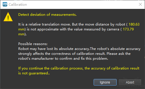
Figure 20 Detect a Measurement Deviation
Image acquisition completed
The interface after the the completion of the image acquisition is shown in Figure 21 below. It is necessary to determine whether the currently recognized calibration point meets the requirements from Tips. If so, click the To Next Step button. If not, please manually add the calibration points by moving the robot through the teach pendant or Mech-Viz software. Check the Manually Add More Images button, and click the Add Single Calibration Board Image And Record Pose button to collect images again.
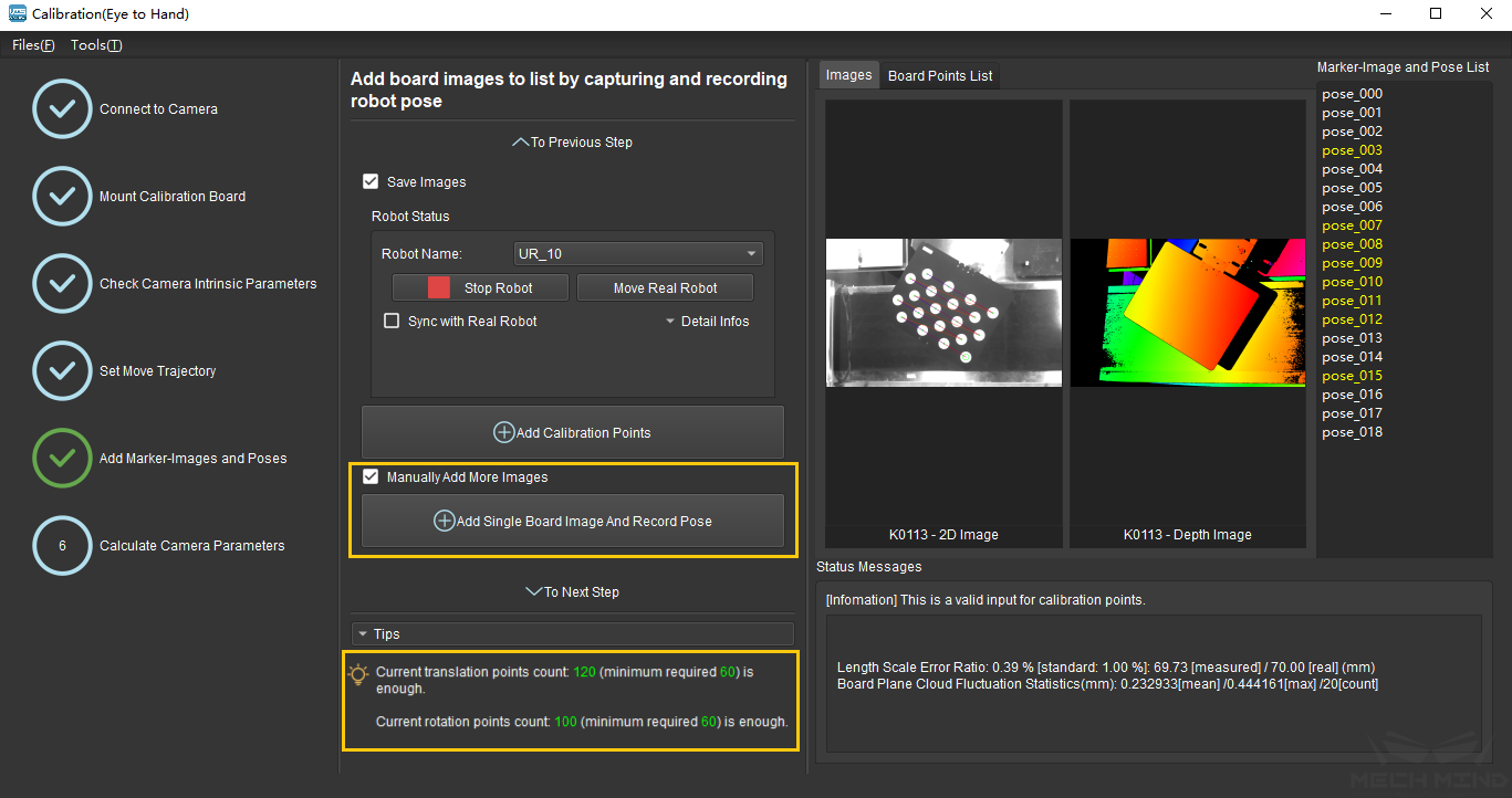
Figure 21 Image Acquisition Completed
Calculate Camera Parameters
Calculate Camera Parameters
In the Calculate Camera Parameters interface, click the Calculate Camera Parameters Results button. Confirm and save the calibration data accordingly. The calibration result and the point cloud showing the calibration error will be displayed on the right part of the window, as shown in Figure 22.
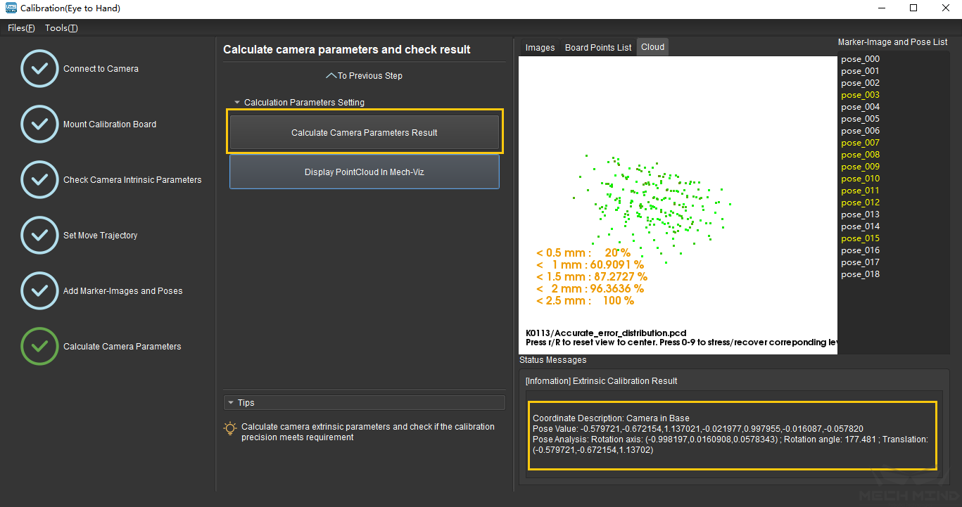
Figure 22 Camera Calibration Results
Display PointCloud in Mech-Viz software
As shown in Figure 23 below, click the Display PointCloud in Mech-Viz button.
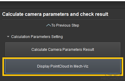
Figure 23 Display Point Cloud in Mech-Viz
Next, in Mech-Viz, select the robot tab. Click the Configure Robot button, and in the pop-up that appears, choose the correct robot type. After which, click the Sync Robot button. The above steps are shown in Figure 24 below.
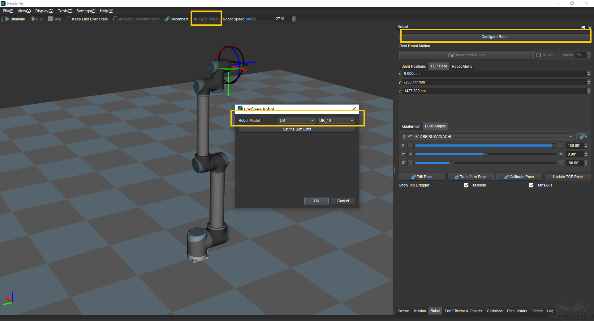
Figure 24 Sync Robot in Mech-Viz
Select the Scene tab, and adjust the ground height accordingly, as shown in Figure 25.
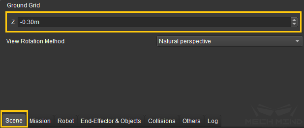
Figure 25 Adjust the Ground Height in Mech-Viz
Finally, the point cloud of the calibration board will be displayed as shown in Figure 26.
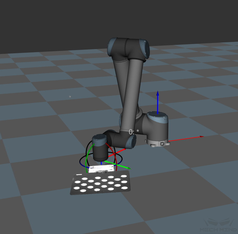
Figure 26 Point Cloud of Calibration Board in Mech-Viz