Eye To Eye
Double cameras calibration is to calibrate the pose relationship between the two cameras. Currently, ETE is used to achieve the calibration of the double cameras pose relationship. Using double cameras calibration can expand the camera field of view and improve the point cloud’s quality of the two cameras’s overlapping part. As shown in the figure 1.
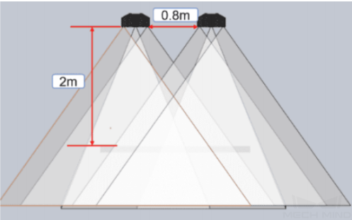
Figure1 Double cameras Field of View
Double Cameras Calibration Method
Multiple random board poses
Calibration premise: The two cameras used have the same resolution. Camera field of view (2D&3D) overlapping area covers the entire working area.
Use Mech-Viz or the control handle to move the robot to place the calibration plate in the field’s center of the two cameras’s view. At this time, the cameras can be connected to collect images to check the position of the calibration board in the field of view. From into the calibration pre-configuration. Add calibration point method select “Multiple random calibration board poses”, calibration setup select “EyeToEye”. As shown in the figure2.
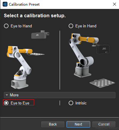
Figure2 Select the Calibration Installation Method
After entering the calibration interface, connect two cameras and choose one of them as the main camera. as shown in the figure 3.
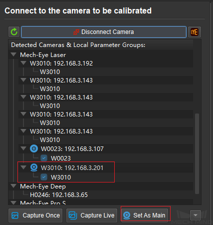
Figure3 Set the main camera
Then calibrate according to the ETH “Multiple random calibration board poses”calibration method. The data displayed on the interface is all the data of the main camera, and the data of the sub-camera will be generated synchronously. After the calibration, the extrinsic parameter data of the two cameras will be generated at the same time. At this time, the ETE calibration is completed.
Calculate from the calibrated extrinsic parameters directly
After calibrating the extrinsic parameters of the two cameras separately by ETH, use ETE to calculate the pose relationship of the two cameras. Open the calibration interface, select ETE for the calibration installation method, enter the calibration interface, In the “Choose the method of adding calibration points”, select “Use the calibrated extrinsic parameters to calculate directly”, and select the extrinsic parameter data of the last calibration, as shown in the figure 4.

Figure4 Select the Method of Adding Calibration Points
After the setting is completed, enter the calibration interface and no need to connect the camera. Directly enter the “calculate camera parameters”. Click Calculate Camera Parameters Result to get the pose relationship of the two cameras. Click Display PointCloud in Mech-Viz to generate a fused point cloud. If the point cloud fusion effect is not good, the extrinsic parameters of the two cameras need to be re-calibrated. The point cloud is shown in the figure 5.
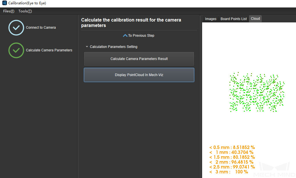
Figure5 View PointCloud
Check the fusion effect of double cameras calibration by building a project in Mech-Vision
The construction of the project is shown in the figure 6. Pay attention to check the “Trigger Control Flow When No Output” and “Trigger Control Flow Output”.
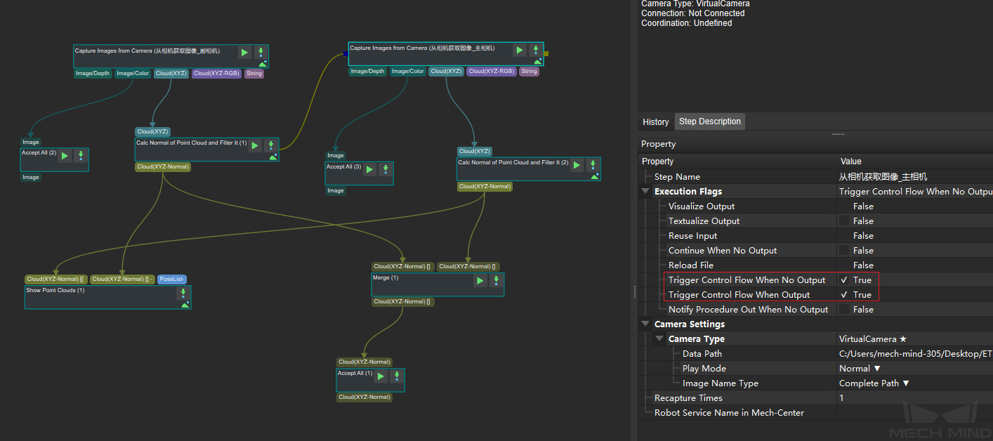
Figure6 Project Construction
Run the “Merge Data” Step to display the merged point cloud. The point cloud output after merging is the fused whole point cloud, as shown in the figure below 7, and you can click the upper left corner View as Whole| 1 | 2 to switch points cloud.
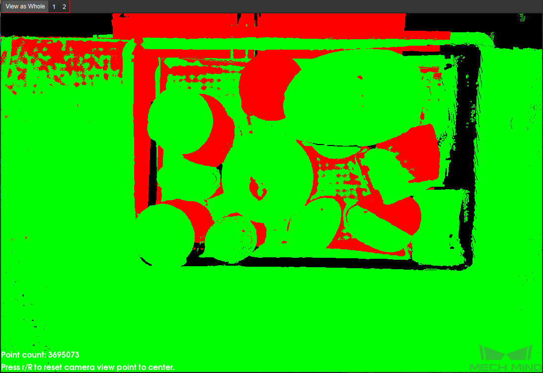
Figure7 Fusion PointCloud