Inspect and Analyze Calibration Results
For the calibrated extrinsic parameters, it is necessary to check whether the calibration accuracy meets the requirements. If the error fall outside the normal range, the user should diagnose and solve the problems that are responsible for the error before recalibrating to obtain qualified extrinsic parameters.
Inspect Calibration Results
Inspect the extrinsic parameters
After the calibration calculation is complete, the Calculate Camera Parameters interface will display the calibration result and the point cloud showing the calibration error, as shown in Figure 1 below. The error point cloud shows the deviation between the calculated value and the actual value of the feature points on the calibration board.
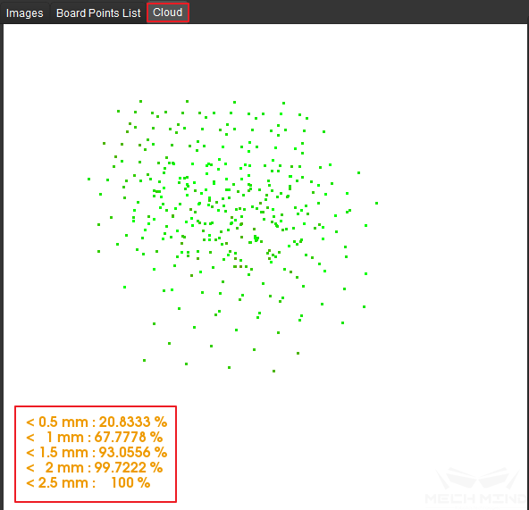
Figure 1 Point Cloud Displaying Calibration Error
The color of the point represents the error level (one error level per 0.5mm of deviation). The darker the color is, the greater the error of the point. Pressing the number keys 0-9 will highlight the points in the corresponding error level (where 0 corresponds to points with error less than 0.5mm, 1 corresponds to points with errors between 0.5mm and 1mm, etc). As shown in Figure 2, pressing the number key 0 will highlight all points with error less than 0.5mm.
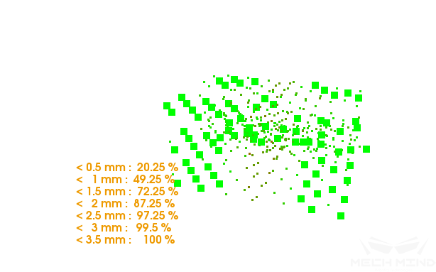
Figure 2 Points with Calibration Error Less than 0.5mm
Similarly, as shown in Figure 3, pressing the number key 5 will highlight all points with error between 2.0mm and 2.5mm.
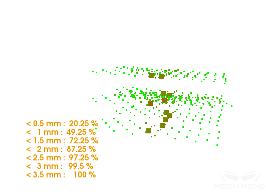
Figure 3 Points with Calibration Error between 2.0mm and 2.5mm
The calibration error will be synchronized in the Log window on the bottom of Mech-Vision interface, as shown in Figure 4 below.
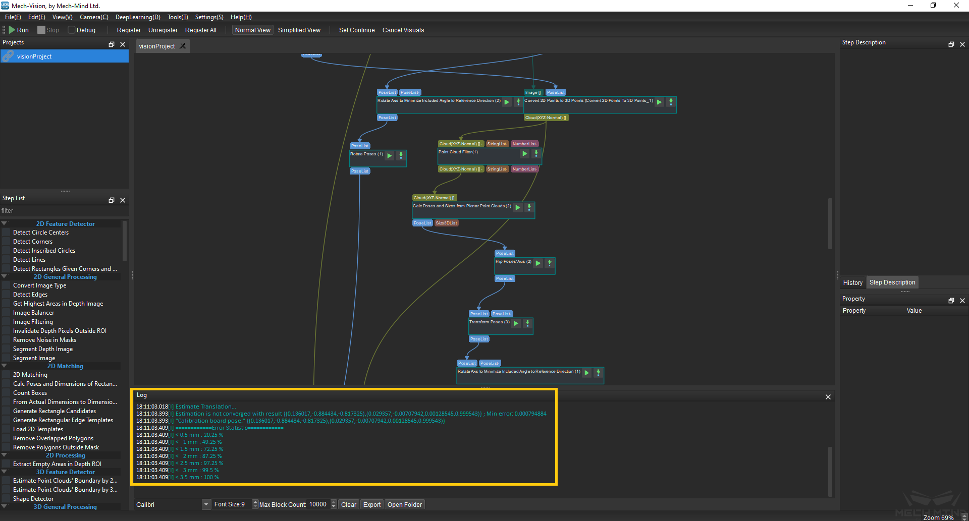
Figure 4 Calibration Error Shown in the Log Window
The point cloud displayed in Mech-Viz can be used to inspect the calibration results roughly.
Roughly inspect the extrinsic parameters for ETH
After obtaining the extrinsic parameters using the ETH method, move the robot into the view of camera and click the Display PointCloud in Mech-Viz button. The point cloud should be roughly consistent with the robot model if the calibration accuracy is high, as shown in the Figure 5 (be aware that the simulation cannot match the real robot completely, and thus cannot be used to fine-tune the extrinsic parameters).
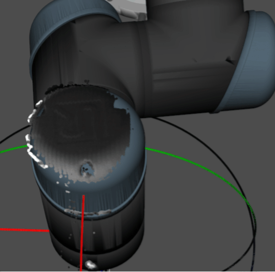
Figure 5 Roughly Inspect the ETH Calibration Results in Mech-Viz
Roughly inspect the extrinsic parameters for EIH
When using the EIH method, place the calibration board on the ground and capture images of the board from multiple different poses. Then, observe if the point cloud of the calibration board deviates noticeably in the robot base coordinate system, as shown in Figure 6.
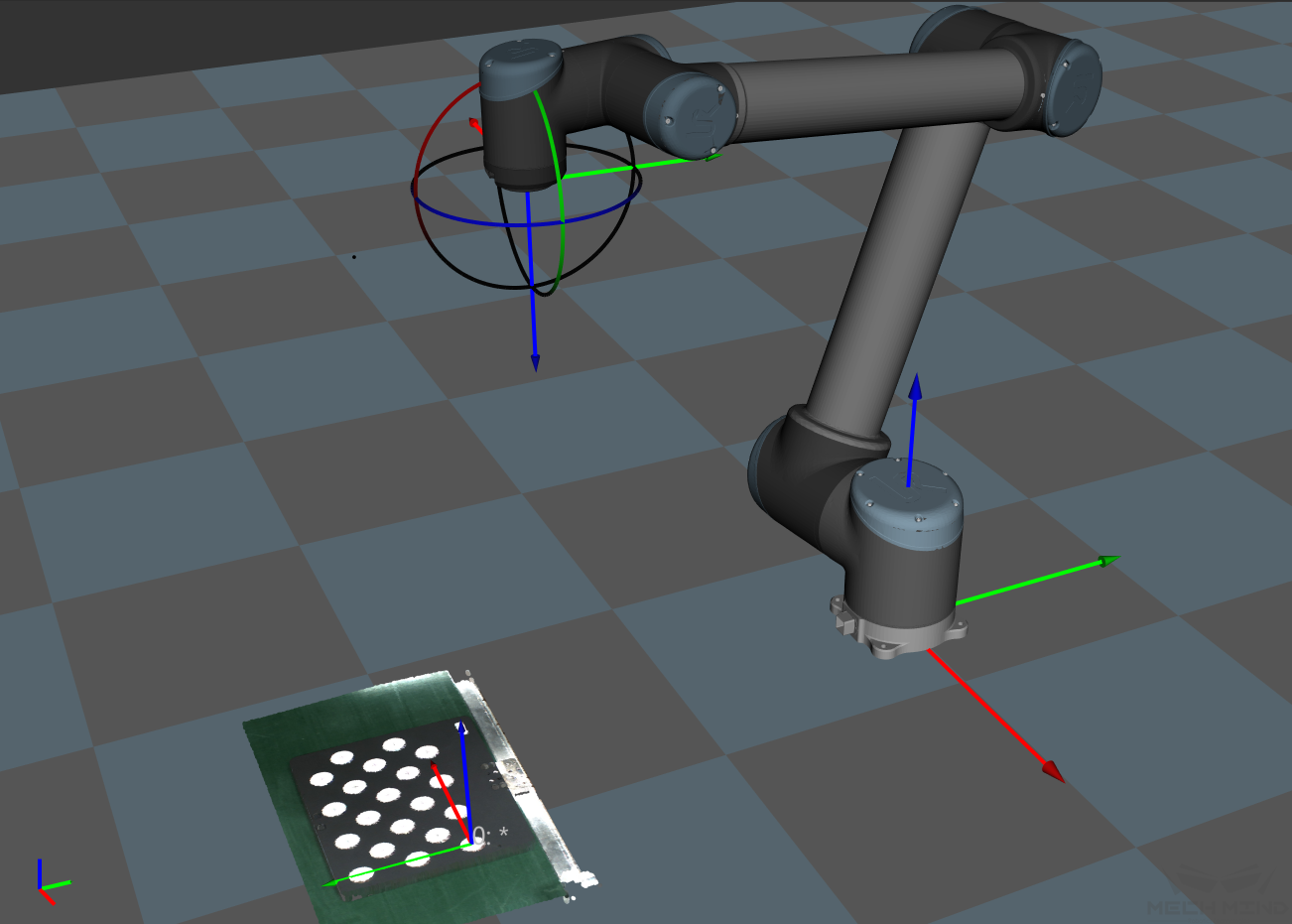
Figure 6 Roughly Inspect the EIH Calibration Results in Mech-Viz
Attention
When using the EIH method, robot poses cannot be obtained in real time if no robot is connected. It is required to enter the current pose before checking the point cloud in Mech-Viz. Do not fine-tune the extrinsic parameter according to the rough inspecting results.
Analyze Calibration Results
Evaluate the calibration results
In general, the standards for acceptable calibration error in the point cloud are as follows:
For common projects, all data points should have errors lower than 3mm (< 3mm: 100%).
For high-precise projects, all data points should have errors lower than 2mm (< 2mm: 100%).
For palletizing and depalletizing projects, all data points should have errors lower than 5mm (< 5mm: 100%).
The above standards are just listed as references. Please follow the specific accuracy requirement of the real application.
Factors affecting the calibration accuracy
If the calibration accuracy is below standard, the user must follow the following instructions to troubleshoot the source of the errors.
Inspect the Accuracy of Calibration Data
Calibration data refers to the calibration points data generated during the calibration process and is stored in calib_data.json. This file records data such as the flange poses and calibration points’ position for every imaging pose. When loading the calibration data, select the Load the calibration data with a virtual camera option, and the software will automatically load the data in this file.
Inspect three main aspects of this data:
Check if the Euler angles change between different sets calibration points (excluding the rotating sets)
Click a pose in the Marker-Image and Pose List. Select Board Points List to see the flange pose of the current calibration point set, as shown in Figure 7 below.
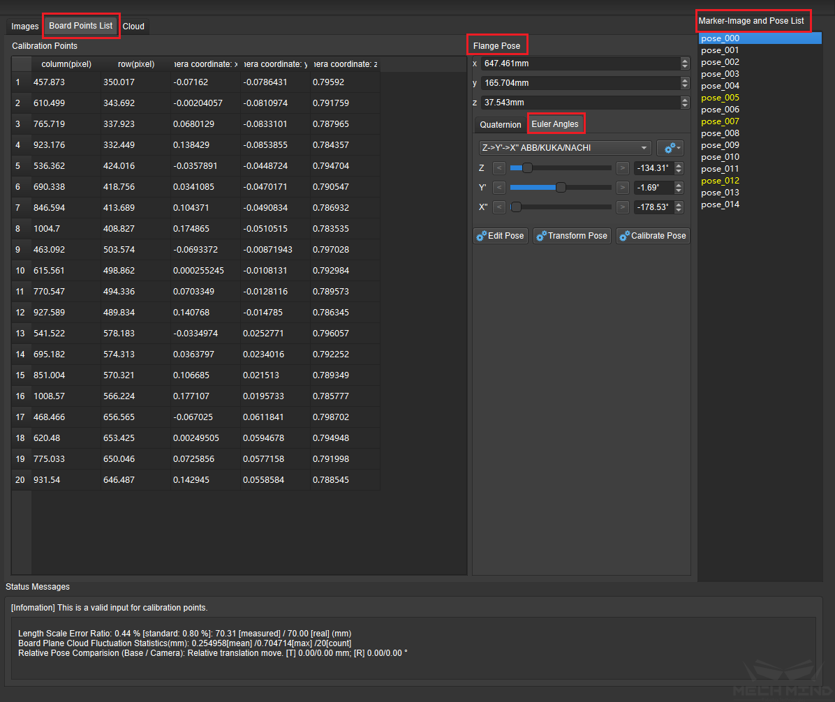
Figure 7 Check Flange Poses of Sets of Calibration Points
Note
In Figure 7, column(pixel) and row(pixel) represent the pixel coordinates of the center points of the calibration circles in the current 2D image; camera_coordinate:x(m)/y(m)/z(m) represents the coordinates of the center points relative to the camera coordinate system in the current depth image.
During the calibration process, the robot will move along its base coordinate or flange without rotating, meaning the Euler angle will be consistent throughout the entire procedure. Depending on the precision level of the robot, the Euler angle might fluctuate differently. If the fluctuation exceeds 1 degree, the robot might have lost its zero position or have bad precision.
Solution: in the above situation, hand-eye calibration should not be continued. The user should check the robot’s zero position and fix the imprecision problem before continuing to calibrate.
Check if the “Length Scale Error Ratio” of the calibration points sets exceeds the standard values
After selecting a pose in the Marker-Image and Pose List, the Status Messages box below will display the Length Scale Error Ratio of the current image. If it exceeds the standard value, the calibration point will turn to yellow to warn the user. As part of the intrinsic parameters check result, Length Scale Error Ratio can partly reflect the current error in the camera intrinsic parameters.
Solution: for projects will low precision requirements, intrinsic parameters with errors that slightly exceed the standard may still be used. For situations where high precision is required or the errors greatly exceed the error, it is recommended to recalibrate the intrinsic parameters or replace the camera.
Note
Errors in intrinsic parameters will affect the calibration result, but if it is within the normal range, it is generally acceptable.
Check if the max value of the “Board Plane Cloud Fluctuation Statistics” exceeds 3mm
Board Plane Cloud Fluctuation Statistics represents the overall fluctuation of the plane containing the coordinates of all the circles’ center points. Every calibration points set has its own Board Plane Cloud Fluctuation Statistics. This value directly influences the accuracy of the extrinsic parameters, and the higher a project’s precision requirements are, the lower the fluctuation value should be. Generally, the max acceptable value for the fluctuation is 3mm. If more than three calibration points sets have fluctuation statistics greater than 3mm, the user should troubleshoot the problems and recalibrate. Potential factors that might cause this are as follows:
The 3D camera exposure parameters are not optimized. It is likely that the Cloud Smoothing and Outliers Removal options are turn off or that the camera gain is turned on.
Solution: Change Cloud Smoothing and Outliers Removal to “Normal”, set Gain to zero, and adjust the 3D exposure parameters accordingly. If the point cloud of the calibration circles is still fragmented, on-site shading is required.
The second source of the fluctuation occurs when multiple random board poses method is used to calibrate for the ETH setup. If the calibration board is not firmly installed on the robot’s flange and the speed of the robot is too fast, the calibration board might vibrate during the calibration process, thus causing excessive point cloud fluctuation.
Solution: Lower the speed limit on the robot, install the calibration board firmly, and extend the wait time before capturing a new image at each waypoint.
Check the Length Scale Error Ratio and Board Plane Cloud Fluctuation Statistics as shown in Figure 8 below.
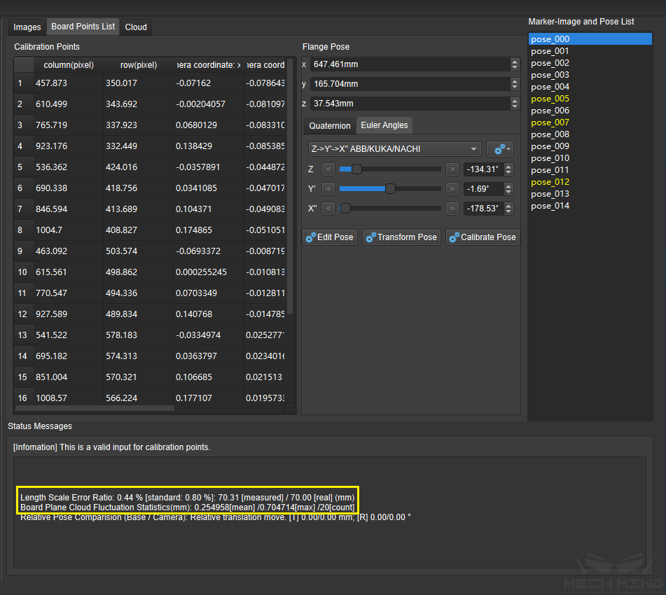
Figure 8 Check Intrinsic Parameters and Point Cloud Fluctuation
Recalculate the Rectification Parameters
After troubleshooting the above problems, please recalibrate the camera and check if the result meets the requirement. If so, finish the calibration process. If not, click the Calculation Parameters Setting button and check the Recalculate Rectification Parameters option to recalculate the result.
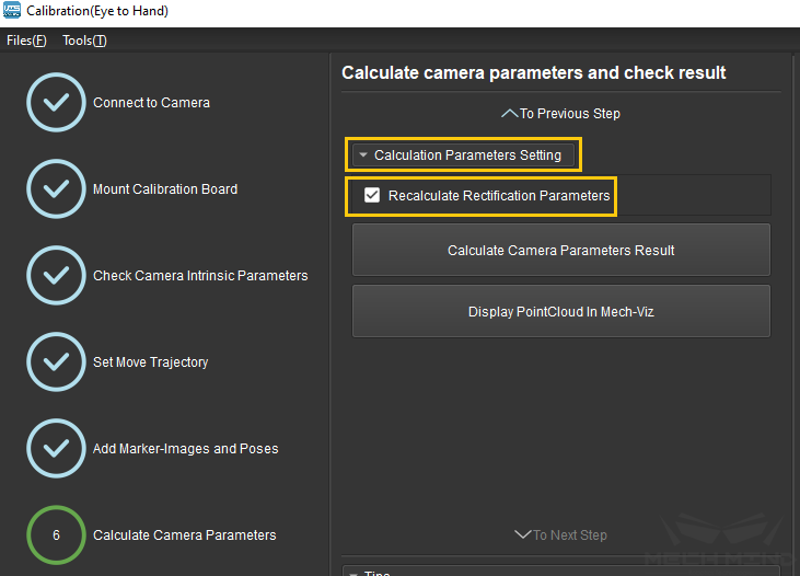
Figure 9 Recalculate Rectification Parameters
Attention
Before checking the Recalculate Rectification Parameters option, please create a copy of the extri_param.json file and rename it to factory rectification parameter.
Now, recalibrate the extrinsic parameters until it reaches the required precision.
Note
After calibration, adjust 3D exposure parameters in Mech-Eye Viewer software according to the production requirements.