Preparation for Calibration
Depending on the relative position between the camera and the robot, the hand-eye calibration can be divided into three types:
Eye To Hand (ETH): the camera is installed on a stationary stand independent from the robot.
Eye In Hand (EIH): the camera is installed on the flange located at the end of the robot.
Eye To Eye (ETE): two cameras are installed on stationary stand(s) independent from the robot.
Install/Place the Calibration Board
Choose a calibration board: pick one whose circles are clearly visible and without obvious scratches or deformations.
For ETH: mount the robot-specific bracket for calibration board onto the robot flange, and then install the calibration board onto the bracket. Make sure that the calibration board is rigidly attached, and that the board is parallel to the XY plane of the robot’s flange coordinate system.
Note
If an undetachable end effector is connected to the robot flange, you can attach the calibration board directly to the end effector.
For EIH: place the calibration board in the center of the object plane, where target objects are to be placed.
Figure 1 below shows the installation/placement of the calibration board for ETH (left) and EIH (right).
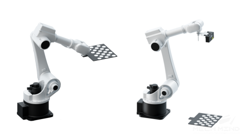
Figure 1. Installation/Placement of the calibration board
Move the robot to the starting point for calibration after you have installed/placed the calibration board. Figure 2 shows the starting point for ETH (left) and EIH (right).
For ETH: the starting point is the center of the camera’s field of view, at the lowest height in the robot’s task space (the robot will move up during calibration).
For EIH: the starting point is the camera’s scanning position, at the lowest height in the robot’s task space (the robot will move up during calibration).
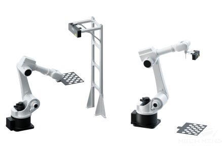
Figure 2. Robot starting point for calibration
Note
If you use the TCP touch method to perform calibration, then the calibration board should be placed on the object plane for both ETH and EIH.
Connect to the Robot
The following steps only apply to robots that can be connected through Mech-Center.
Connect to the robot according to the process in Add a Robot Model and Connect the Real Robot.
Check the robot’s connection status, that is, check if the camera, robot and IPC are successfully connected via the router. Make sure that the robot can be controlled by Mech-Viz and its pose is consistent with the simulation results of Mech-Viz.
Once the robot is successfully connected, an icon will show up in Mech-Center, as shown in Figure 3 (The displayed robot model should match the actual robot).
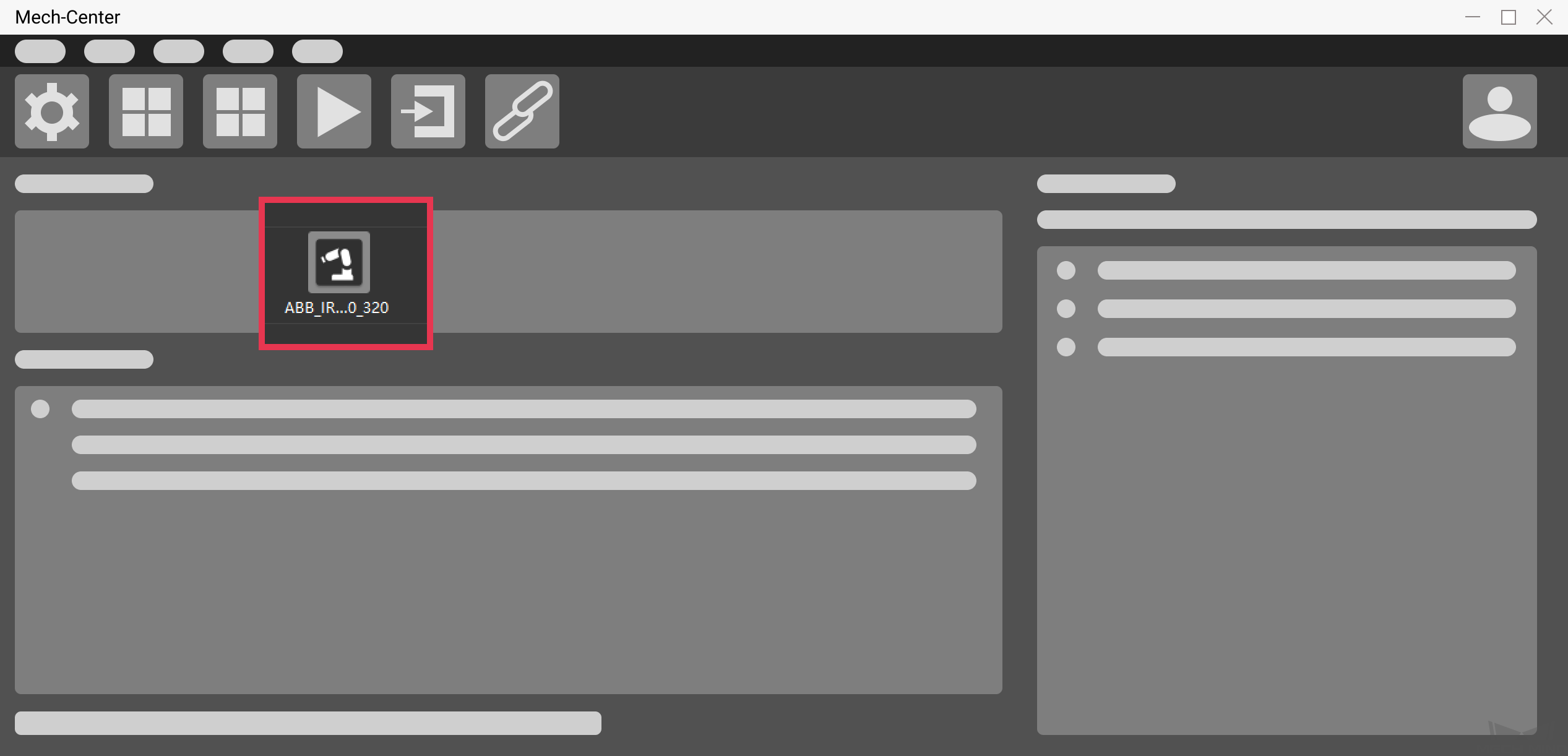
Figure 3. Mech-Center interface after robot connection
Adjust Camera Settings for Point Cloud Generation of the Calibration Board
Open Mech-Eye Viewer and adjust camera settings, please refer to Mech-Eye Viewer for detailed instructions.
Adjust the settings under 2D Scanning to make sure that the 2D image of the calibration board is clear and neither overexposed nor underexposed.
Adjust the settings under 3D Scanning to make sure that the point clouds of the circles on the calibration board are complete and have clear contours. For smoother point clouds and more accurate calibration result, we also recommend setting Cloud Smoothing and Outliers Removal under Point Cloud Processing to
Normal.If the on-site lighting conditions are not ideal and affects the quality of 2D images and point clouds, you can use shading or supplemental light to improve the lighting conditions.
Make sure the obtained point clouds of the circles on the calibration board are complete and have clear contours, as shown in Figure 4.
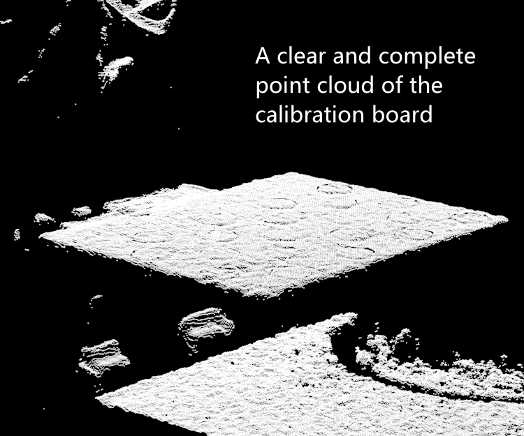
Figure 4. Point cloud of calibration board