FAQ
Explanation for Factory Rectification Parameters
Explanation and Use of “Recalculate Rectification Parameters”
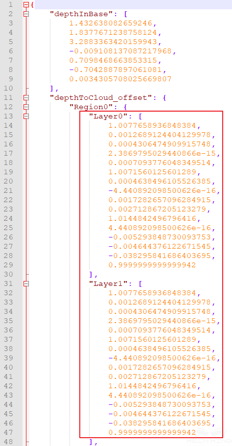
The rectification parameters are stored in the camera extrinsic parameter file extri_param.json, as shown in the following figure 1:
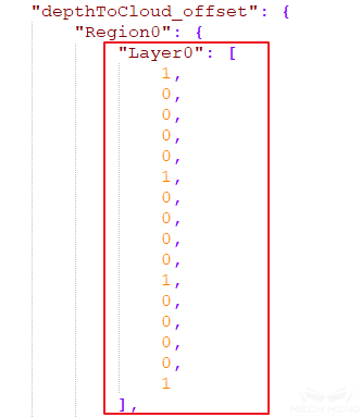
The rectification parameters will be a unit matrix if the camera does not have rectification parameters, as shown in the figure below 2:
If you check Recalculate Rectification Parameters and click ‘calculate’, the optimal rectification parameters will be refitted according to all current calibration points data, and the rectification parameters in the extrinsic parameter file will be updated.
Factory rectification parameters: The factory rectification parameters are based on the focal length of the camera and its maximum workspace. The advantages and disadvantages of using the factory rectification parameters:
Advantages: Using factory rectification parameters, extrinsic parameters that represent the accuracy of the entire working space can be calculated under the condition that the number of calibration points is small and the workspace is not fully marked. The factory rectification parameters are preferred when the TCP touch method is used and the calibration space is limited after the robot is installed with the calibration board and the workspace cannot be fully marked.
Disadvantages: The actual on-site robots and the space of calibration moving trajectory are different. The factory rectification parameters cannot guarantee the best results every time. Using Recalculate Rectification Parameters can obtain better results if the workspace is fully marked.
Attention
After obtaining the extrinsic parameters that meet the accuracy requirements with the factory rectification parameters, it is not recommended to check Recalculate Rectification Parameters for higher accuracy if the workspace is not fully marked.
Solutions When Factory Rectification Parameters are Invalid
Invalid factory rectification parameters means that the on-site rectification parameters are updated but the factory rectification parameters are not backed up; or the camera is not marked with the factory rectification parameters, etc.
Solution when using TCP touch method
In this case, the problem of inaccurate rectification parameters can be solved by adding multiple sets of touch points and then calculating.
Add multiple sets of touch points: place the calibration board at the bottom middle of the workspace, poke three points with the tip and take a picture to generate a touch point; place the calibration board on the edge of the workspace, poke points again to generate a touch point;
Divide the workspace into different layers and add multiple sets of touch points, as shown above (generally, three layers and two points per layer are enough).
Solution when using multiple random calibration board poses
In this case, the problem of inaccurate rectification parameters can be solved by fully marking the workspace and checking Recalculate Rectification Parameters.
Non-six-axis Robot Calibration
Four-axis Robot
Four-axis robots include truss robots, SCARA robots, and palletizing robots, etc. Considering the frequency of use, Mech-Viz is only adapted to a small number of SCARA and palletizing robots (the adaptation range will continue to be expanded in the future).
Tip fixation when using TCP touch method
Mount the sharp tip on the end of the robot and check whether the tip is stably fixed at one point and installed in the center of the flange by rotating the fourth axis. The TCP of the four-axis robot cannot be marked. The XYZ values of the TCP need to be measured manually.
How to adjust the Z-direction for four-axis robot calibration
When using the multiple random calibration board poses method, the four-axis robots’ lack of rotational degree of freedom will result in the robot lacking the rotational values during the calibration process. After the calibration is completed, the Z direction of the extrinsic parameters needs to be manually adjusted:
Find the base coordinate position of the robot;
Place the calibration board on the working plane parallel to the XY plane of the robot base coordinate, usually the ground;
Measure the distance from the base coordinate of the robot to the working plane. In Mech-Viz, set the ground height to this distance. As shown in Figure 3 below:
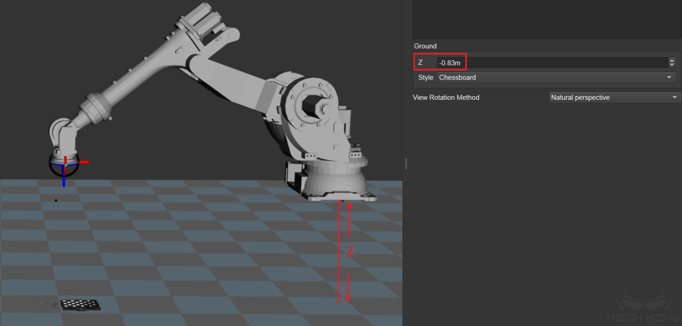
Figure 3 Adjust the Ground Height in Mech-Viz
Adjust the Z-direction value of the extrinsic parameters so that the point cloud of the calibration board is exactly on the working plane in Mech-Viz. Then, the Z-direction adjustment is completed.
Instructions for truss robots
Depending on the type of robot and the defined position of the base coordinate of the truss robot, it is difficult to adjust the Z direction based on the base coordinate position. Therefore, only the TCP touch method is recommended for truss robot.
The most common setup for truss robot is to mount the camera on the third axis:
EIH: In this case, the truss robot becomes a three-axis robot as the fourth axis cannot be used. The user can only send fixed angles to the robot through the adapter.
ETH: There is a limited number of fixed scanning points and the offset between each scanning point are known. Add the robot base coordinate offset in the adapter each time a different scanning point is used.
Seven-axis Robot/Six-axis Robot with Slide Rail/Five-axis Robot
Note
The six-axis robot with slide rail mentioned here means that the slide rail is integrated into the robot teach pendant. Thus, it is equivalent to a seven-axis robot.
The TCP touch method is recommended for the above three types of robots.
Requirements for seven-axis robots using multiple random calibration board poses method
When there is no suitable sharp tip on site or the sharp tip cannot be mounted, the multiple random board poses method can be used to calibrate the seven-axis robot. During the calibration process, it is necessary to limit the movement of one of the axes and idealize it as a six-axis robot. The rest of the operations are roughly the same as the calibration of the six-axis robot.
How to Calibrate When the Euler Angle Type of the Robot is Uncertain
Get Euler Angle Type
When the Euler angle of the robot is unknown, use the Get Euler Angle Type under the Tools menu bar to get the Euler angle type of the robot, as shown in Figure 4 below:
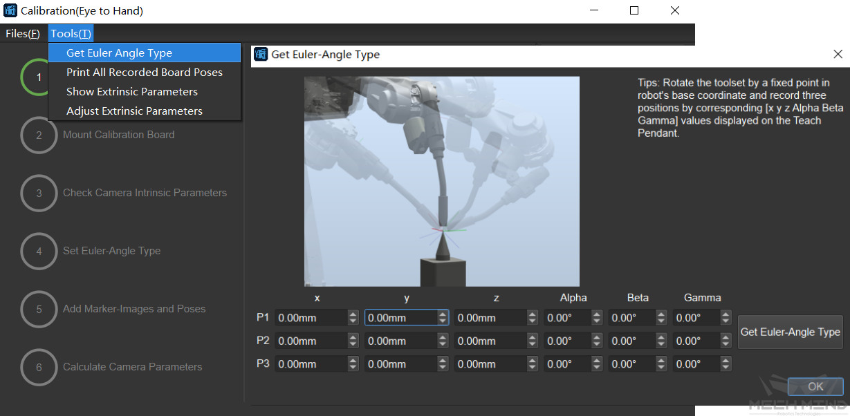
Figure 4 Get Euler Angle Type
Adjust the robot’s pose to obtain three different poses where the tip mounted at the end of the robot and the tip on the desktop touch each other. Fill in the pose of the robot on teach pendant after each touch. After which, click Get Euler Angle Type to obtain the recommended Euler angle.
How to Calibrate if There is Only a Sharp Tip Mounted at the End of the Robot with Known TCP but No Suitable Tip Fixed onto the Workspace
Since the accurate Euler angle type of the robot is unknown, the Euler angle cannot be inputted according to the correct type when using the TCP touch method for calibration.
In this case, switch the pose on the robot teach pendant to the TCP pose so the pose of the tip is obtained.
Touch three points in turn, read the values of XYZ on the teach pendant and input. Choose any Euler angle type and enter any constant value. Make sure that the Euler angles of the three input poses are the same.
Solutions for When A Large Number of Calibration Point Cloud Fluctuations are Out of Tolerance During Long-Distance Calibration and Adjusting Camera Parameters Does Not Improve
Check the calibration board to see if there are crosses which may cause large fluctuations in the point cloud, as shown in Figure 5 below:
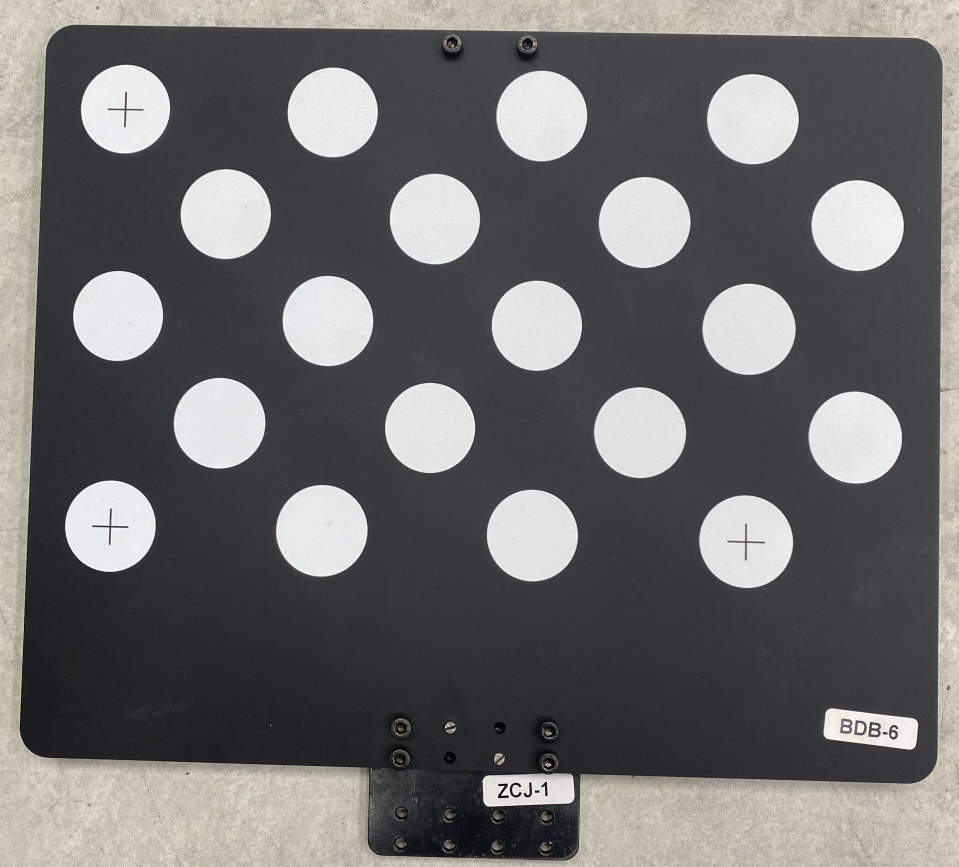
Figure 5 Crosses on the Calibration Board
Find A4 paper to cover the center of each dot (do not cover the edge of the circles). The crosses’ effect on point cloud fluctuation should be reduced after it is done. If the above method still does not solve the problem, try to manually add more poses and delete the poses with severe point cloud fluctuations.
Common Misunderstandings about Calibration
The more calibration points, the better
Too many calibration points may introduce abnormal points, leading to an increase in the overall error ratio. When using the factory rectification parameters to calculate, determine the number of points for each layer according to the camera focal length, the size of the calibration board, etc.
When the focal length is 300-2000mm, it is recommended to use a 2*2 configuration, with four calibration points per layer. The number of layers is generally three. Use four layers for high stacks.
When the focal length is 2000-3500mm, it is recommended to use a 3*3 configuration, with nine calibration points per layer. The number of layers is generally three. Use four to five layers for high stacks.
The calibration range has to cover the entire working area
When using the factory rectification parameters, calibration should be carried out in layers around the center of focus and around the focal length of the camera. When the factory rectification parameters are not used or when it is impossible to calibrate around the camera’s focal length, it is recommended to calibrate the entire working area.
The extrinsic parameters of the calibrated area are accurate, while the extrinsic parameters of excluded area are inaccurate
The error point cloud generated after calibration shows the extrinsic parameters error of the calibrated area. However, it does not mean that the extrinsic parameters of the unmarked area must be inaccurate. On the contrary, when using the factory rectification parameters, the extrinsic parameters of the unmarked area are also usually accurate.