Manually Add Calibration Points
This chapter will introduce the method to add calibration points manually in situations where the robot cannot be controlled by Mech-Viz.
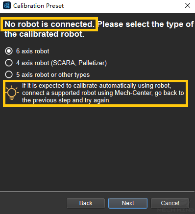
First, select the calibration type and robot model according to the real robot in the preset window, as shown in / Figure 1/ .
Select Robot Model
Multiple Random Board Poses
If multiple random board poses is chosen to add calibration points, please follow the process below:
Set Euler-Angle Type
The euler angle type need to be set in step 4.
If the type of Euler angle is known, please check Known Euler-Angle Type and choose the corresponding type.
If the Euler angle type is unknown, please do as the following steps, which are also shown in Figure 2:
Click Unknown Euler-Angle Type and then Get Euler-Angle Type.
Install a fixed sharp point in the robot work area, then rotate the tool around this point and record three different robot poses.
Click Get Euler-Angle Type , the Euler angle type will be calculated.
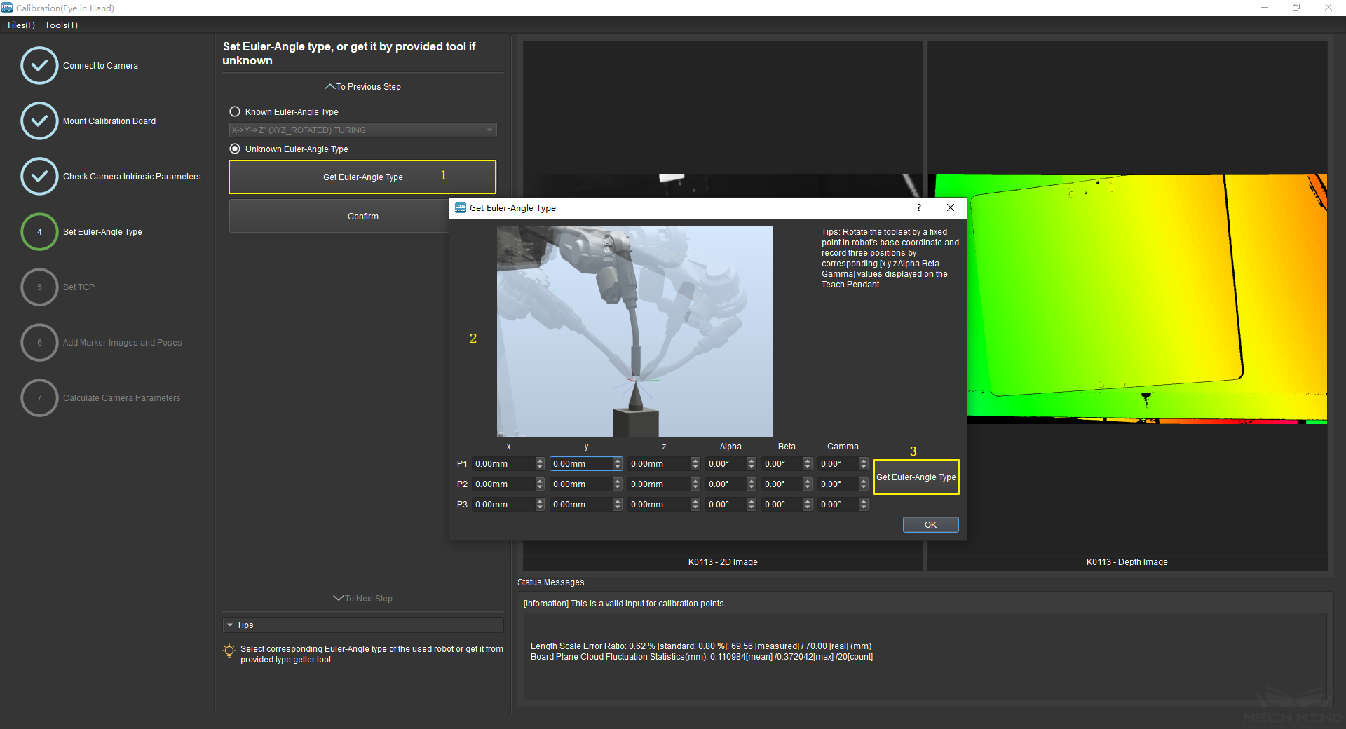
Figure 2 Get Euler-Angle type
TCP Touch
If TCP touch is used to add calibration points, it is also necessary to set the Euler angle. Please refers to Set Euler-Angle Type for the operation.
Set TCP
If the position of TCP relative to the origin of the flange is known, check Known TCP Value and input the X, Y, Z value.
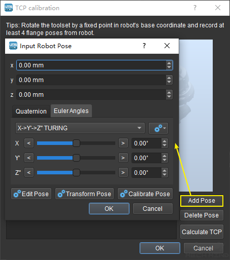
If the position is unknown, check Unknown TCP Value and click the Calibrate TCP button. Touch the fixed point with the sharp point at the end of the robot from at least four different poses. Click Add Pose everytime the robot touches the fixed point, and in the pop-up that appears, enter the current flange pose, as shown in Figure 4. After four sets of poses are recorded, click Calculate TCP.
Calibrate TCP
Attention
Make sure the TCP value is set to 0 in the teach pendant when checking the Known TCP Value option.
Add Marker-Images and Poses
Drive the robot to touch P1, P2 and P3 on the calibration board. Everytime the robot touches a point, click Add Pose and input the current robot pose in the pop-up, as shown in Figure 5.
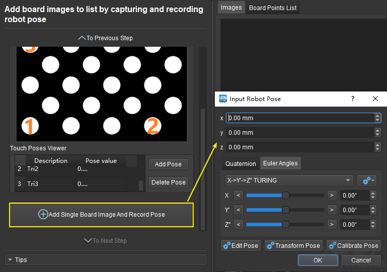
Add Three Poses
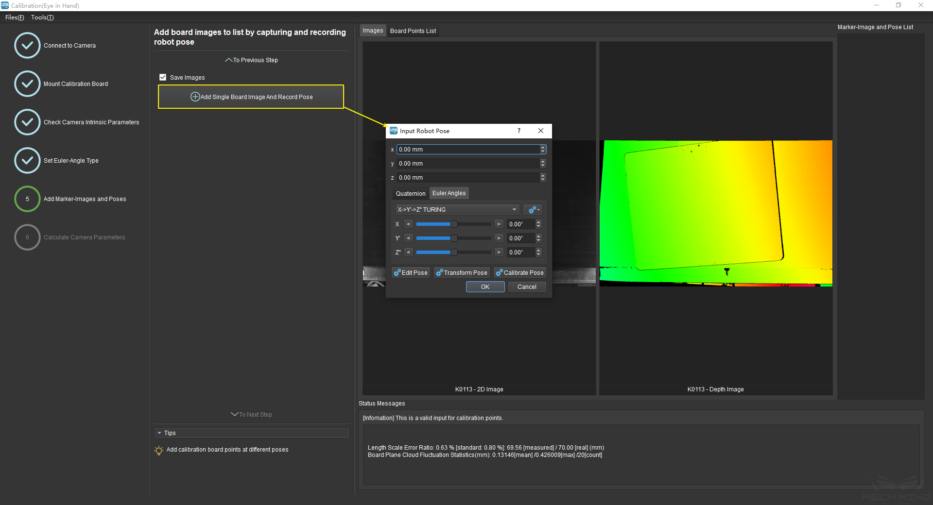
Move the robot to a pose where the camera could capture the entire calibration board. Click the button Add Single Board Image And Record Pose to let the camera take a photo and detect the circles on the calibration board. If the calibration setup is EIH, it is necessary to input the current robot pose in the pop-up window.
Then, click To Next Step to go to the Calculate Camera Parameters page.
Attention
Make sure the calibration board is stationary during the whole process.