Add Calibration Points by TCP Touch
In special cases where the robot cannot be controlled by Mech-Viz or the calibration board cannot be installed, TCP touch is recommended for robot hand-eye calibration. Compared to other methods, TCP touch only needs one set of calibration points to accomplish the task.
Calibration Preset
Select a directory to save calibration results
Launch Mech-Vision and click Camera \(\rightarrow\) Camera Calibration \(\rightarrow\) Select a directory to save calibration results (if a Mech-Vision project is opened, it will use current project directory by default), as shown in Figure 1.
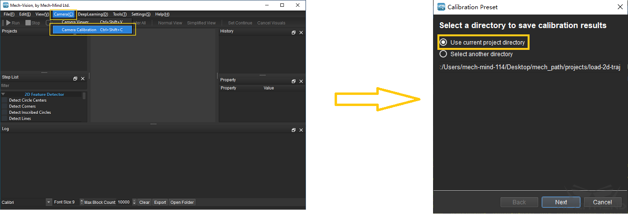
Figure 1 Select a Directory to Save Calibration Results
Select a calibration setup
Select the corresponding calibration type, as shown in Figure 2. Eye to Hand (ETH) will be used in the following section.
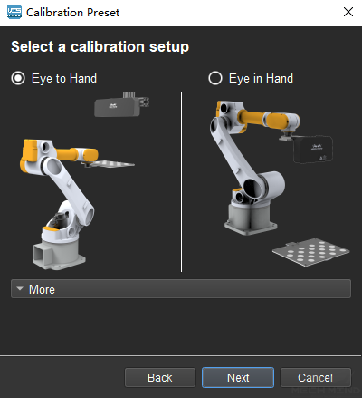
Figure 2 Select ETH Method
Check robot connection status and select a calibration method
If the robot is connected, the window in Figure 3 will be shown. Select Use TCP touch and click the Finish button to enter the calibration interface.
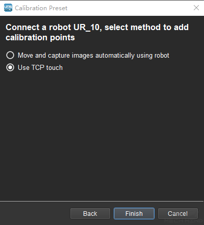
Figure 3 Select a Method to Add Calibration Points
If no robot is connected, select the correct robot type or go back to the previous step and retry after connecting a robot in Mech-Center, as shown in Figure 4.
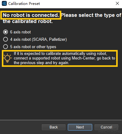
Figure 4 No Robot is Connected
Note
In the following calibration process, a connected 6 axis robot is used as an example. For the details on special types of robots, please refer to TCP Touch.
Connect to Camera
Select the camera
When the network is well connected and the camera works normally, the camera ID will automatically appear under the “Detected Cameras & Local Parameter Groups” list. After selecting the camera, click Connect, and the camera will connect to the Mech-Vision software, as shown in Figure 5 below.
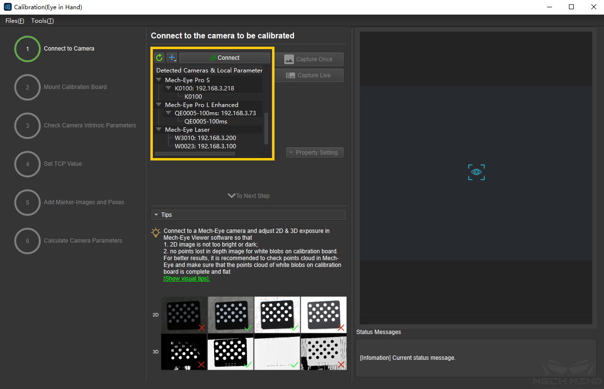
Figure 5 Connect the Camera
Capture images
After connecting to the camera, select Capture Live or Capture Once to view the captured images on the right side of the interface, as shown in Figure 6 below (it is suggested to stop capturing images once the images in the view meet the requirements. Otherwise, multiple refreshes may affect the next calibration step).
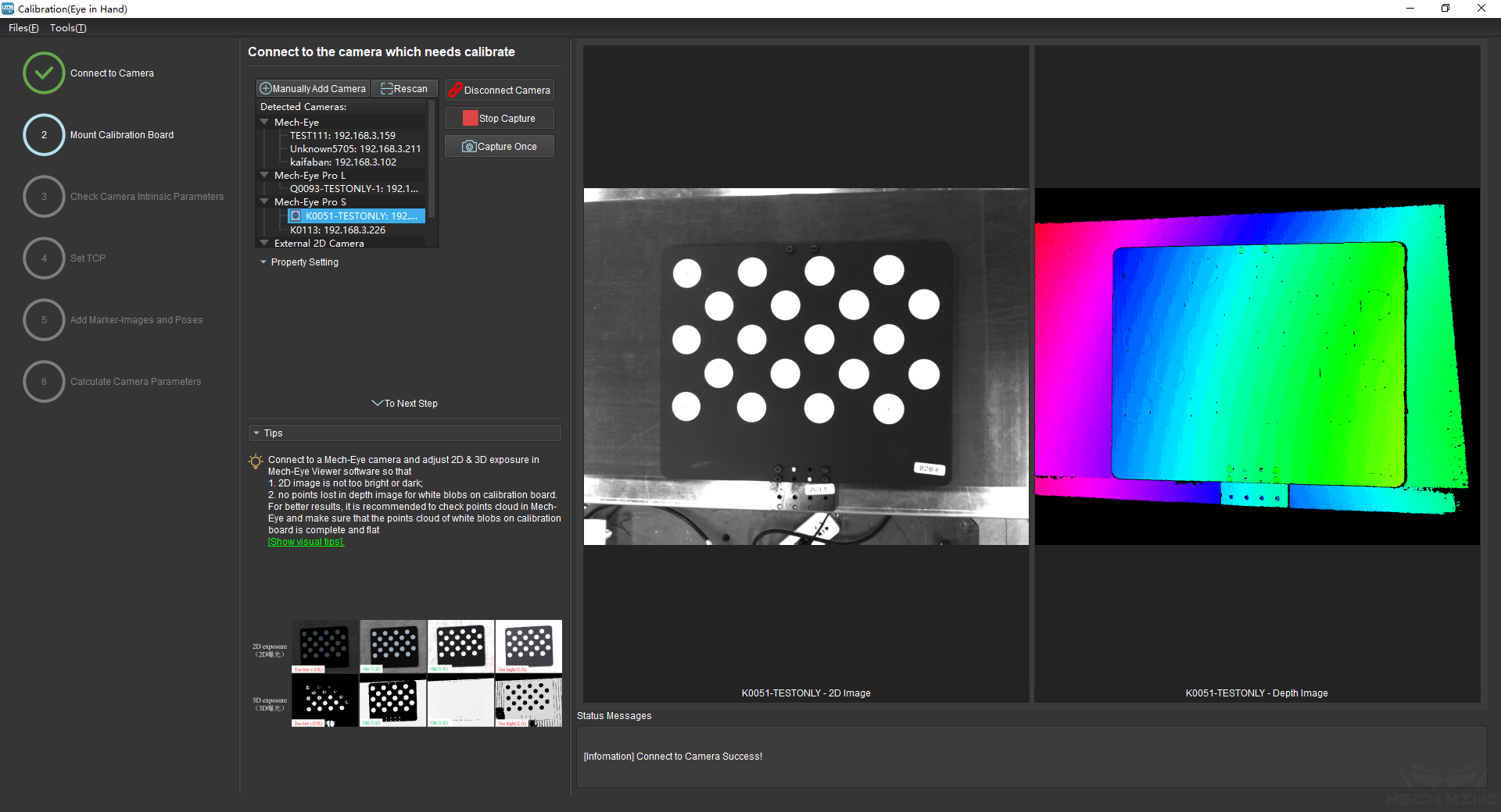
Figure 6 Capture images
Manually Add Camera
If the camera is functioning normally but cannot be found under the list of detected cameras, please manually add the camera IP. Click the + icon, and a dialog box will pop up, as shown in Figure 7 below. Fill in the corresponding camera name and camera IP to add the camera to the detected cameras list. Then, connect the camera following the steps mentioned above.
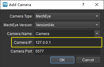
Figure 7 Manually Add Camera
Mount Calibration Board
Select the correct type of calibration board and put it in the camera’s field of view. The operation interface is shown in Figure 8 below.
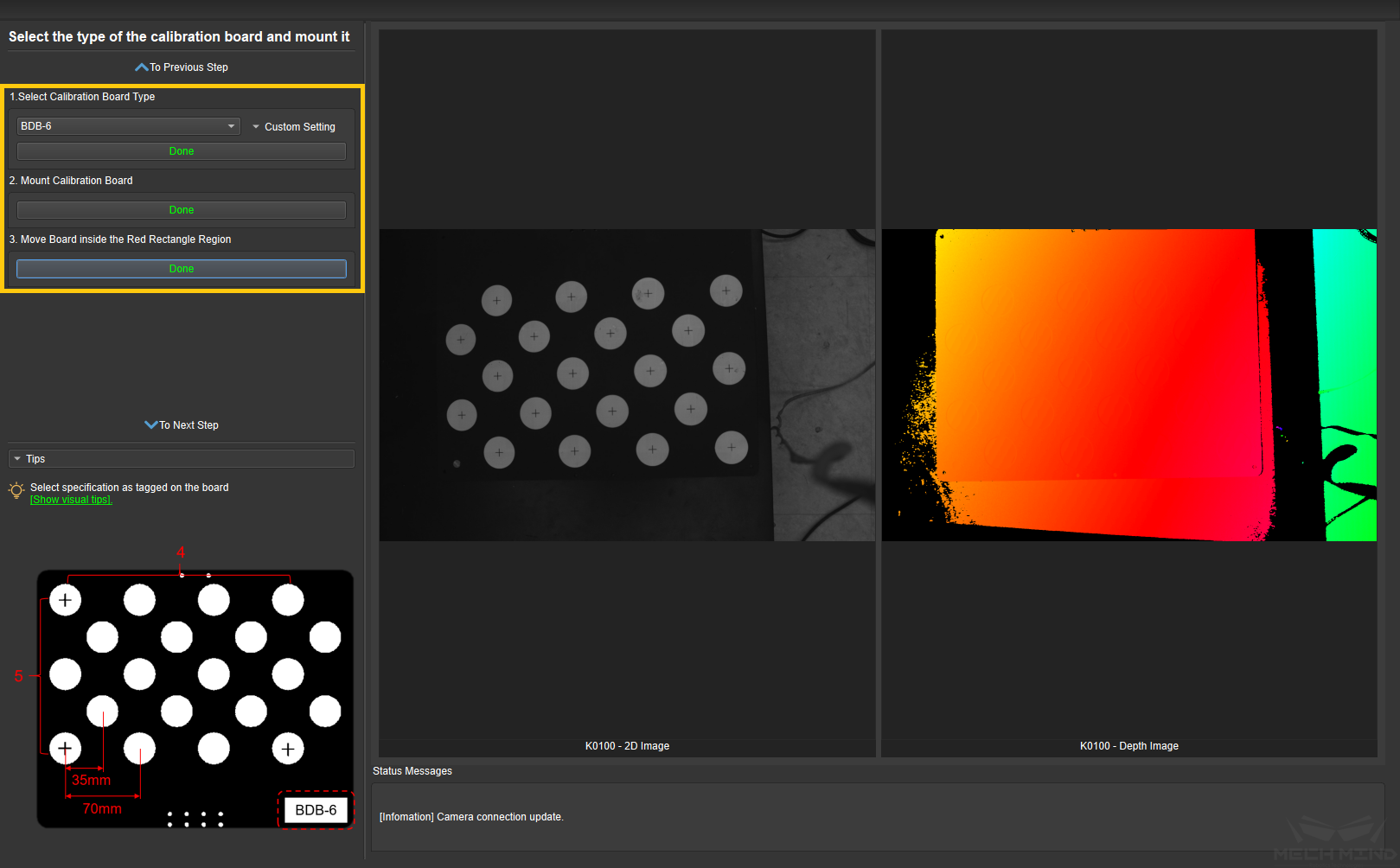
Figure 8 Mount Calibration Board
Specific steps are as follows:
Select the corresponding calibration board model (the name of the model is affixed on the top of the calibration board), and click the Confirm button.
Confirm that the camera is installed on the robot and the calibration board is within the camera’s field of view. Click the Confirm button when finished.
Make sure the calibration board is within the red rectangle in the 2D image, and click the Confirm button when finished.
Check Camera Intrinsic Parameters
Check Camera Intrinsic Parameters
After mounting the calibration board, check if the camera parameters are correct in order to ensure that feature points can be detected during the calibration process. Click the Check Camera Intrinsic Parameters button, and the result of the intrinsic parameter checking will be displayed in a pop-up window. Figure 9 shows a successful intrinsic parameter check.
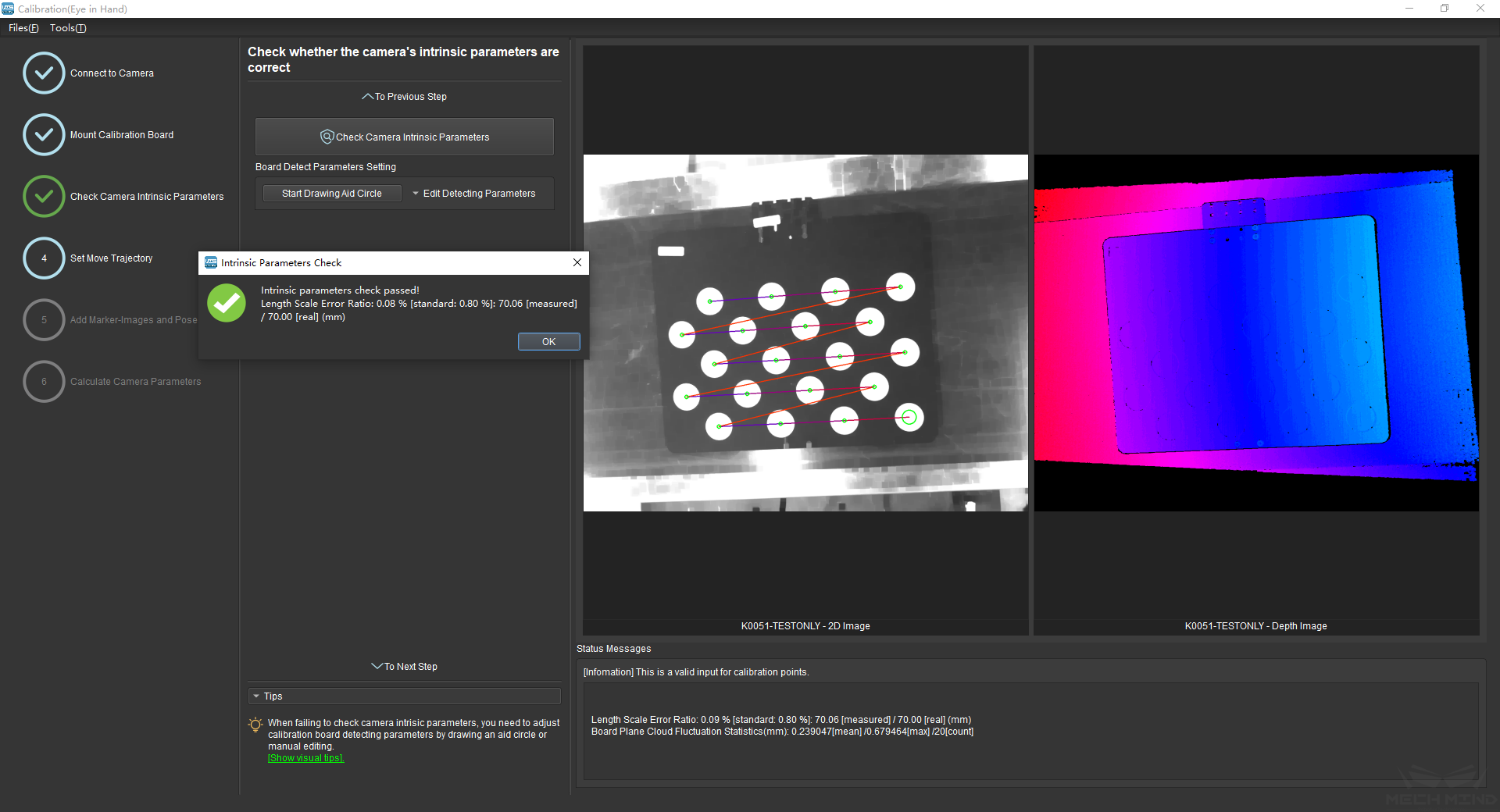
Figure 9 Check Camera Intrinsic Parameters
Generally, when the lighting conditions are good and the camera settings are appropriate, the intrinsic parameter check will pass by simply keeping the default values. Figure 10 shows a successful detection of the feature points.

Figure 10 Detected Feature Points
Draw Aid Circle
If the intrinsic parameter check fails, draw an aid circle or manually adjust the calibration board detection parameters. Select the Start Drawing Aid Circle button and draw a circle coinciding with a circle in the calibration board. After which, the detecting parameters of the circles should change.
If the user chooses to manually adjust the detecting parameters, simply click Edit Detecting Parameters and change the values accordingly.
After completing the above steps, click the Check Camera Intrinsic Parameters button again to get a new result. The steps are shown in Figure 11 below.
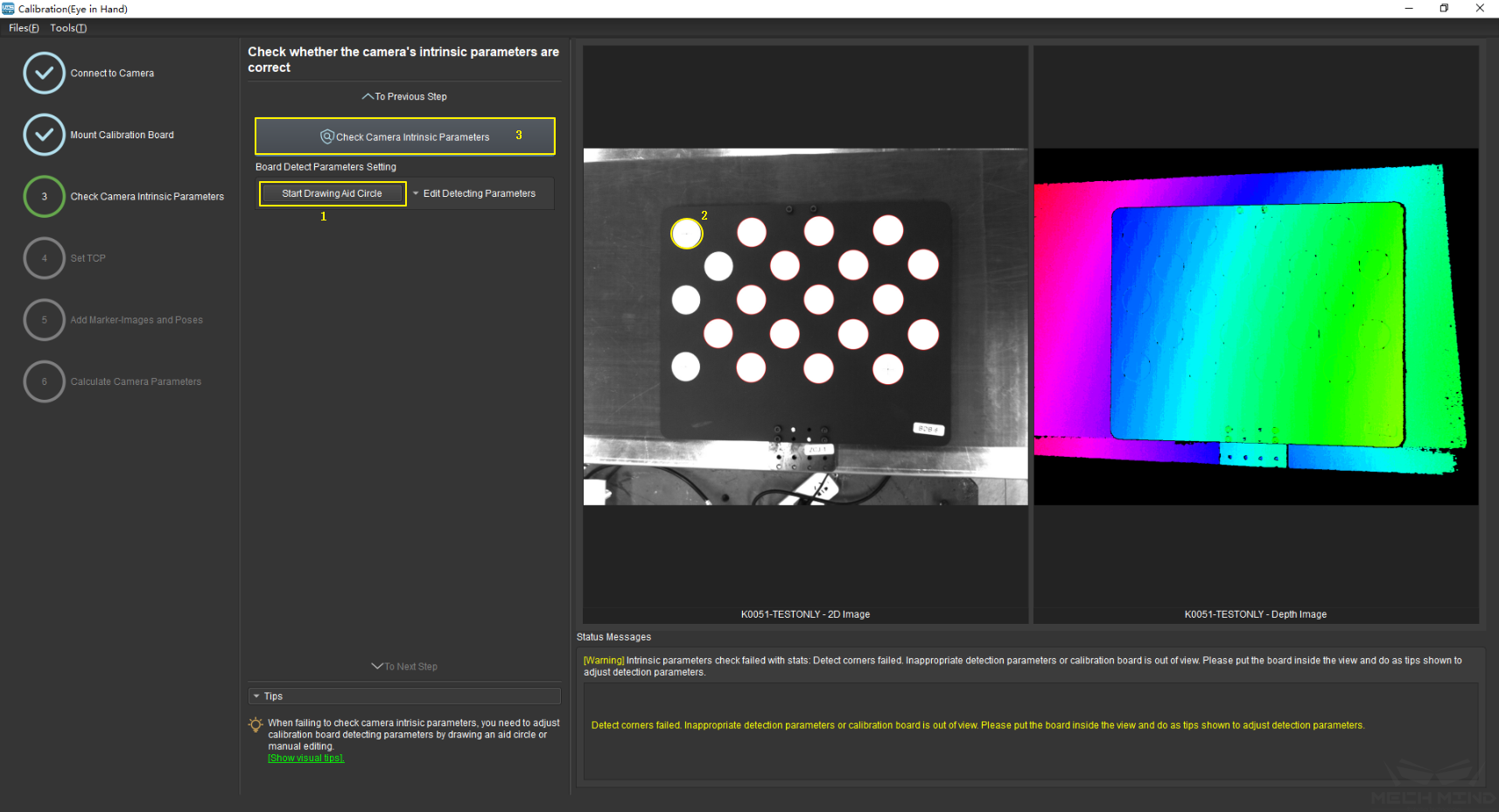
Figure 11 Draw the Aid Circle
Tip
If the calibration circles are too small to be selected easily, the user could right click the 2D image, uncheck Fit to Window, and select Normal Size. Start drawing aid circles after adjusting the size of the image.
If the feature points are still not detected, please adjust the camera settings according to the on-site operating conditions. Detailed information can be found in Mech-Eye Viewer.
Set TCP
Calibrate TCP
In order to accurately measure the pose of the calibration board in the robot base coordinate, it is necessary to obtain the position of TCP relative to the origin of flange (default direction) first.
The Set TCP Value interface is shown in Figure 12 below. If the TCP position is known, please check the Known TCP Value option and input the TCP value. If the TCP position is unknown, please check the Unknown TCP Value option and click the Calibrate TCP button.
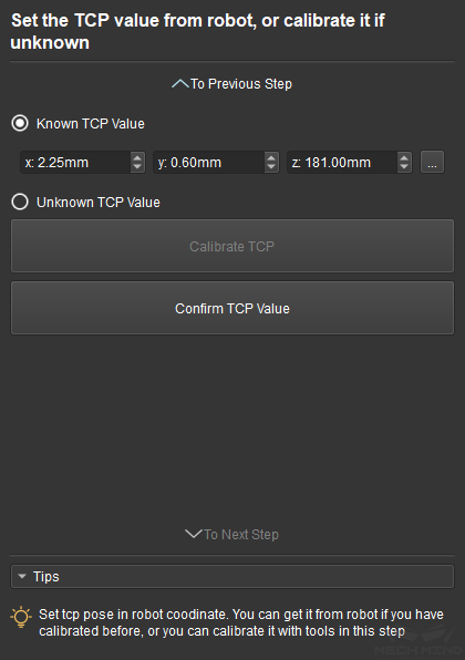
Figure 12 Set TCP
The steps are as follows:
Fix a sharp point in the robot work space. Let the robot touch this point from 4 different directions (namely 4 different poses). Click the Add Pose button every time the robot touches the point and the pose will be shown in the list.
Delete Pose will delete the pose which is not needed.
After adding 4 poses, click Calculate TCP to obtain the position of TCP. The error of calculation is shown in the pop-up window. As shown in Figure 13 below.
After confirming that the TCP position is right, click Confirm TCP Value and To Next Step to finish the TCP calibration.
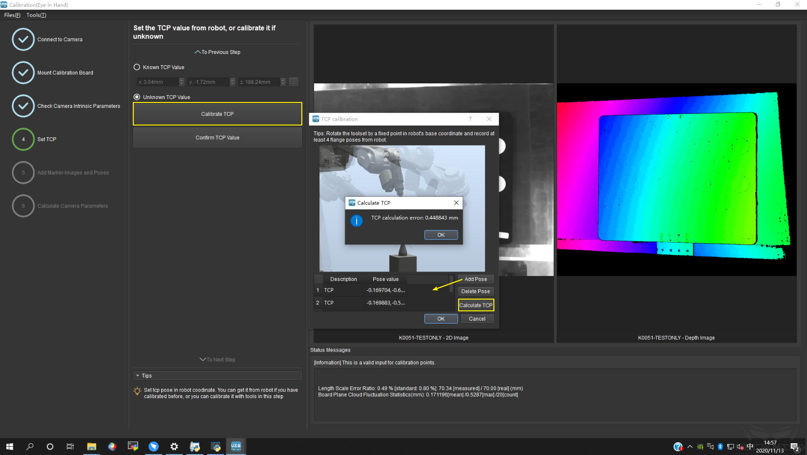
Figure 13 TCP Calculation Result
Tip
Some robots, such as ABB, cannot be controlled by the teach pendant after connecting with Mech-Center. The solution is to disconnect the robot from Mech-Center, move robot to touch the sharp point with the teach pendant, click Add Pose, and manually input the pose which is shown on the teach pendant.
Note
Make sure the TCP value set to 0 in the teaching pendant when checking Known TCP Value.
Add Marker-Images and Poses
Start calibrating after the value of TCP is set.
Drive the robot to touch P1, P2 and P3 on the calibration board. Everytime the robot touches a point, click Add Pose to add the pose into the list. After touching all three points, the three poses will be shown in the Touch Poses Viewer. This is shown in Figure 14.
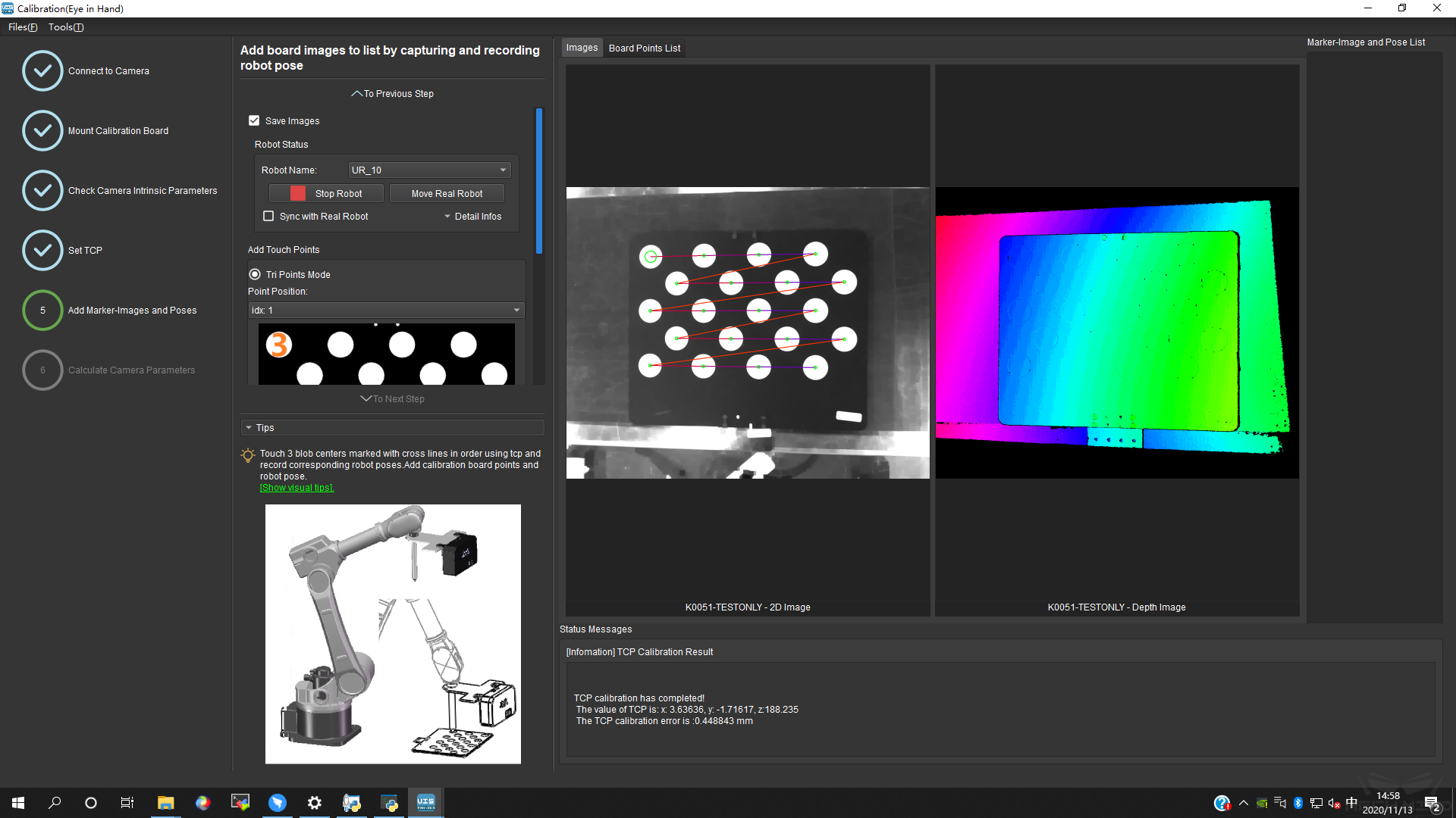
Figure 14 Add Three Poses
The real TCP touch for EIH is shown in Figure 15 below.
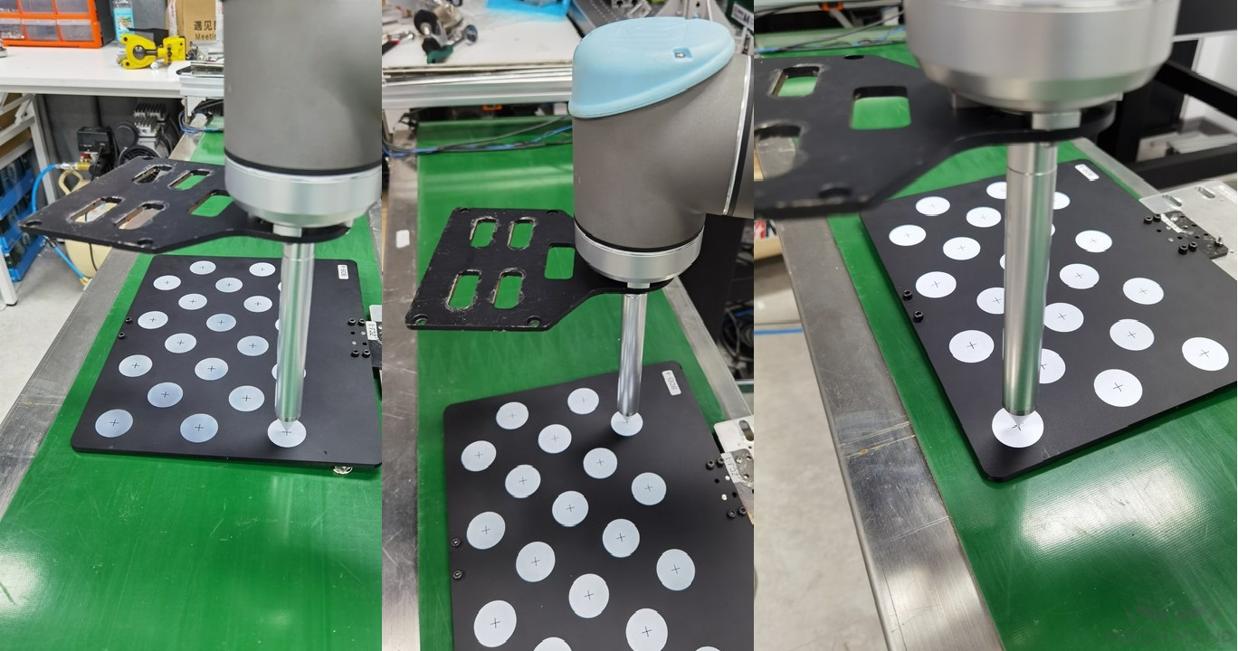
Figure 15 Real TCP touch
Move the robot to a pose where the camera could capture the entire calibration board. Click the button Add Single Board Image And Record Pose to make the camera take a photo and detect the circles on the calibration board. Then click To Next Step to continue to the Calculate Camera Parameters page. The above steps are shown in Figure 16 below.
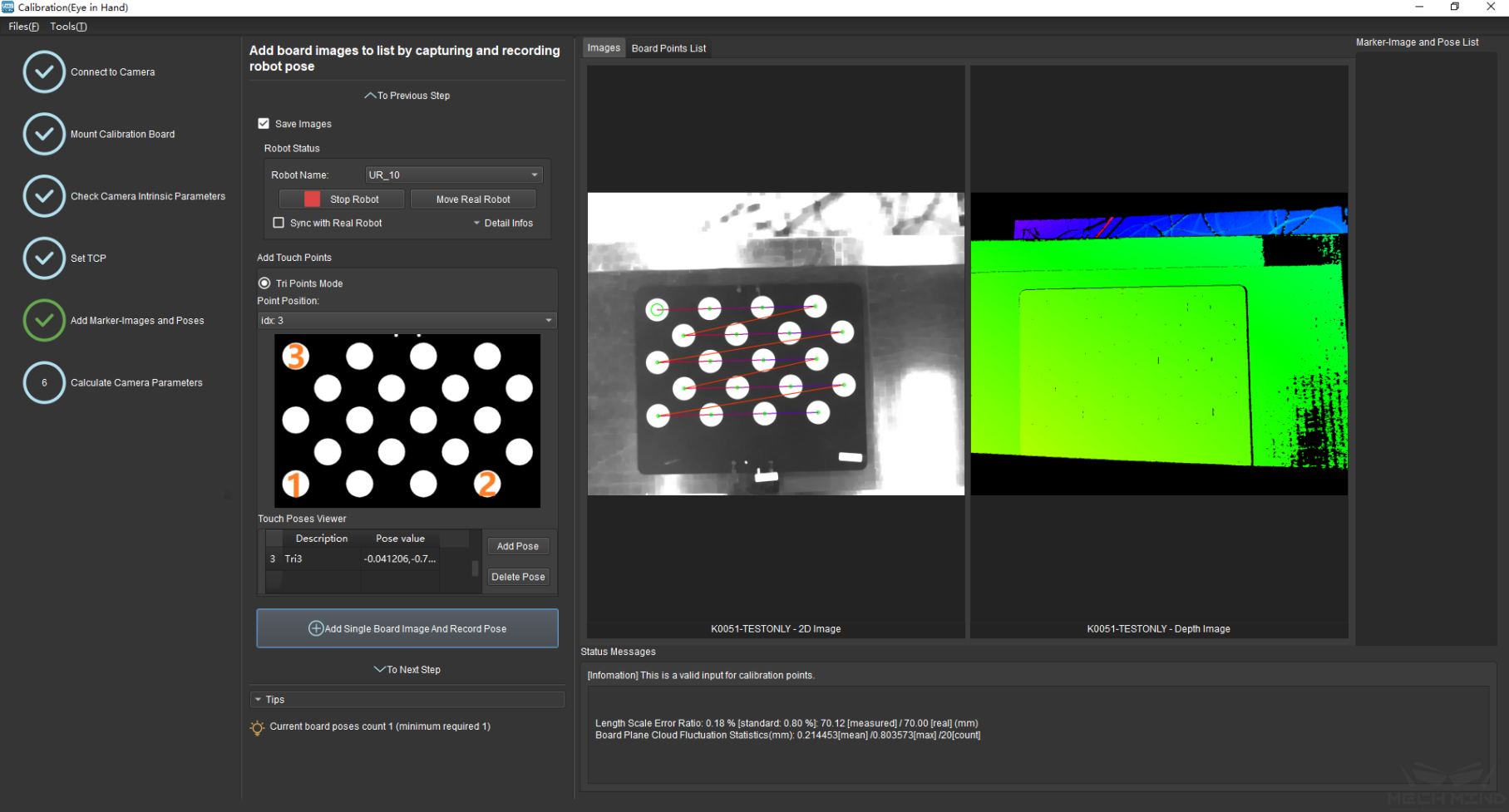
Figure 16 Add Calibration Point
Attention
Make sure the calibration board is stationary in the whole process.
Calculate Camera Parameters
Calculate Camera Parameters
In the Calculate Camera Parameters interface, click the Calculate Camera Parameters Result button. The point cloud showing the calibration error and the calibration result will be displayed on the right part of the window, as shown in `Figure 17<#ETH_TCP_pic17>`__ below.
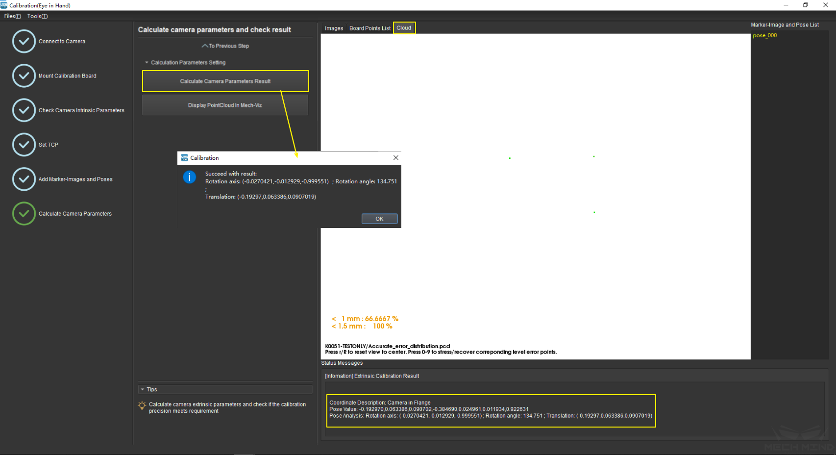
Figure 17 Calculate Camera Parameters
Display point cloud in Mech-Viz
As shown in Figure 18, click the button Display PointCloud in Mech-Viz.
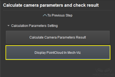
Figure 18 Display Point Cloud in Mech-Viz
Next, in Mech-Viz, select the robot tab. Click the Configure Robot button, and in the pop-up that appears, choose the correct robot type. After which, click the Sync Robot button. The above steps are shown in Figure 19 below.
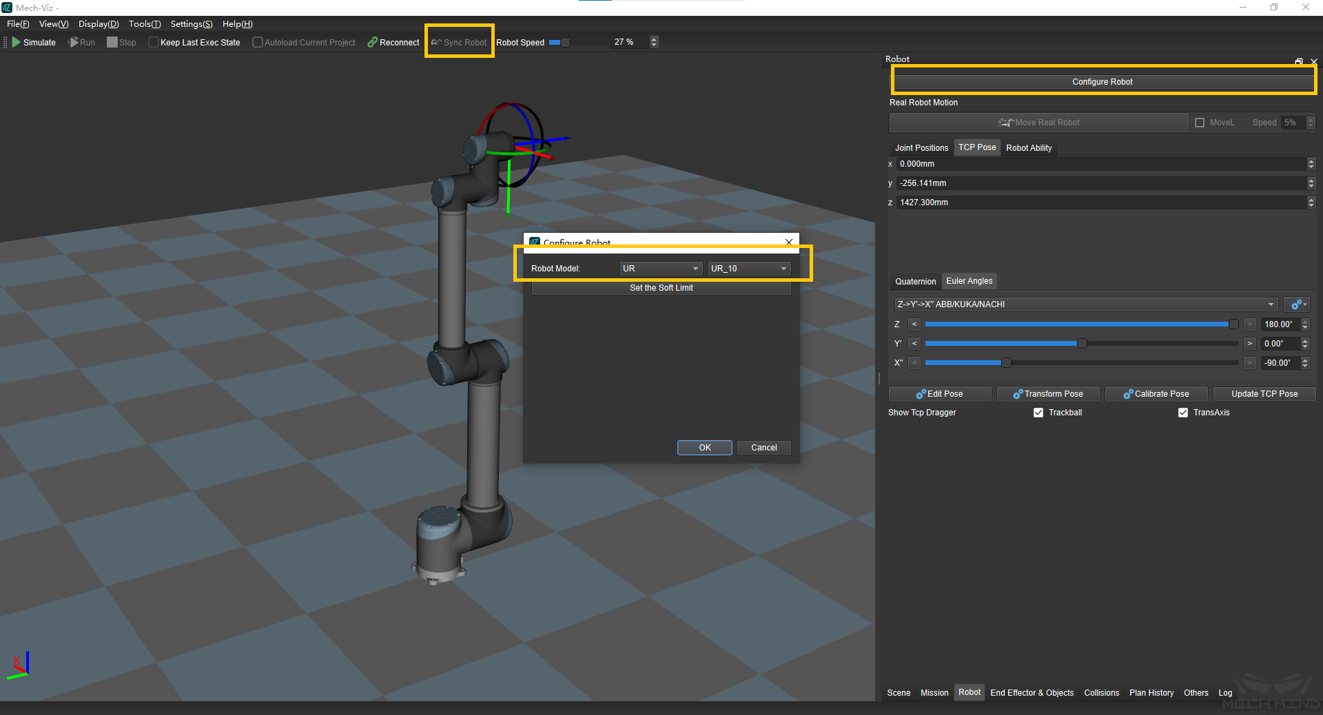
Figure 19 Synchronize Robot in Mech-Viz
Select the scene tab and adjust the ground height, as shown in Figure 20.

Figure 20 Adjust the Ground Height in Mech-Viz
Finally, the point cloud of the calibration board will be displayed as shown in Figure 21.
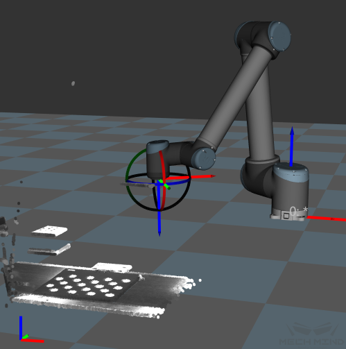
Figure 21 Point Cloud of the Calibration Board in Mech-Viz