Overlapping Planar Workpiece Loading
Application Scenarios
The project is suitable for picking objects that have few features and irregular shapes, are prone to overlaps, and have the same front and back faces which means there is no need to distinguish the two faces.
Mech-Vision Project Workflow
As the workpieces come in large quantities and are prone to overlaps, and as the features are usually at the workpiece edges, only the part of point clouds of the workpiece edges should be extracted for 3D matching after instance segmentation to reduce the interference from the unusable non-edge workpiece features. The workflow is as shown in Figure 1.
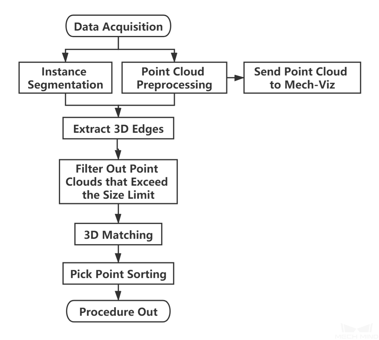
Figure 1. The workflow of a Typical Project for Overlapping Planar Workpieces
Figure 2is a screenshot of the graphical programming of the project.
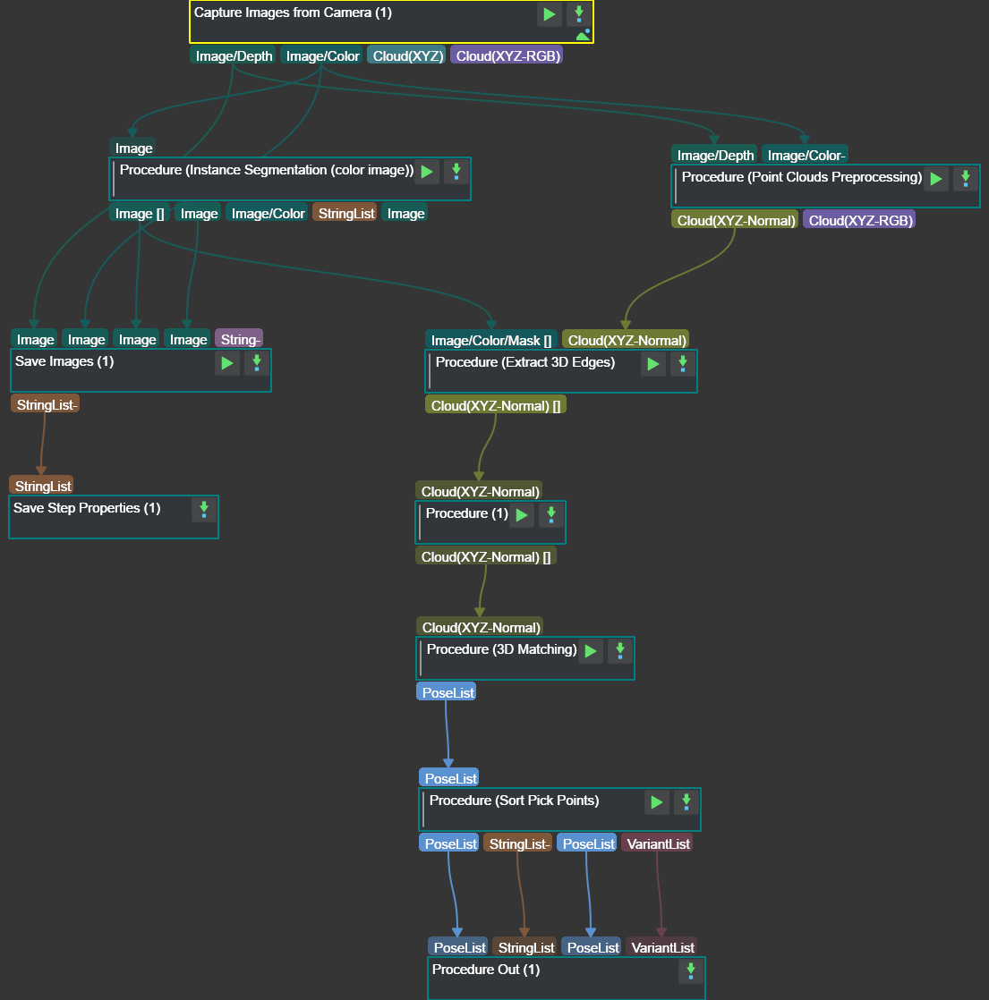
Figure 2. The graphical programming of a Typical Project for Overlapping Planar Workpieces
Steps and Procedures
A Procedure is a functional program block that consists of more than one Step.
Point Cloud Preprocessing
This Procedure facilitates and shortens the processing time for the subsequent calculations. Point Cloud Preprocessing generates a raw point cloud from the depth map and the color image, deletes the outliers, calculates the normals for the point cloud, and in the end extracts the part of the point cloud within the ROI.
For details about this Procedure, please see Point Cloud Preprocessing.
A sample result of Point Cloud Preprocessing is shown in Figure 3.
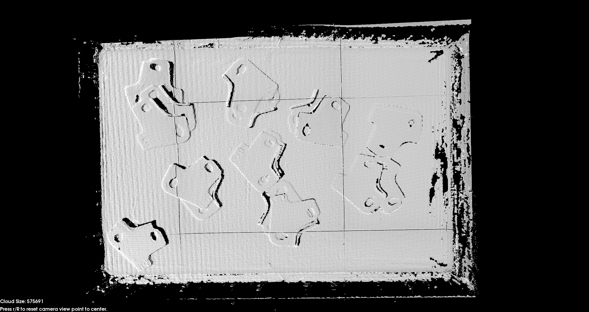
Figure 3. A sample result of Point Cloud Preprocessing
Instance Segmentation (Colored Image)
In this project, instance segmentation by deep learning is used to find the planar projection of the workpieces and generate masks, thus forming the basis for the subsequent task of generating the workpiece point clouds. A sample result is shown in Figure 4.
Please see Instance Segmentation (Colored Image) for details about this Procedure.
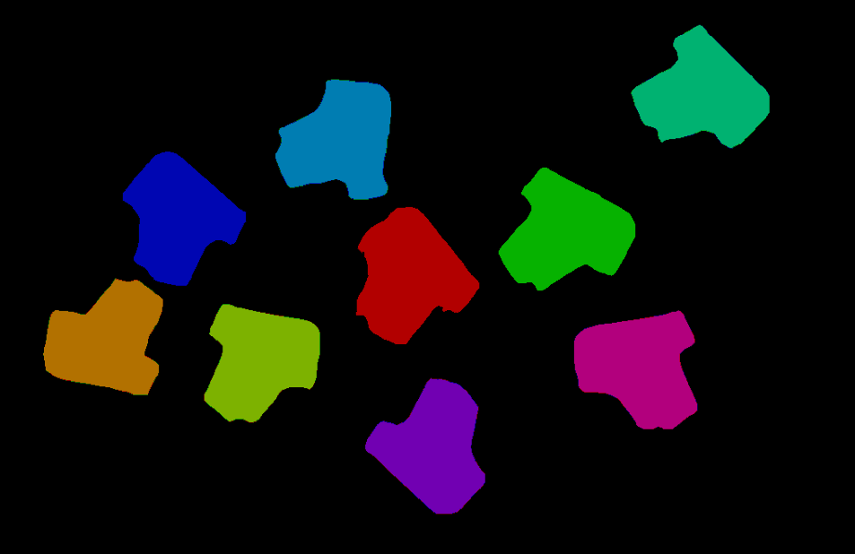
Figure 4. A sample result of Instance Segmentation (Color Image)
3D Boundary Extraction
This Procedure extracts the workpiece edge point clouds after the workpiece point clouds under the masks are obtained. The purpose is to filter out unnecessary point cloud parts to facilitate the subsequent 3D matching.
A sample result is shown in Figure 5.
Please see 3D Boundary Extraction for details about this Procedure.
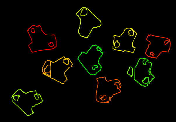
Figure 5. A sample result of 3D Boundary Extraction
Filter Out Point Clouds That Exceed the Limit
After the point clouds of individual workpieces are generated, this Procedure filters out point clouds that have point counts excceding the limit and thus affect 3D matching to improve the accuracy of matching.
A sample result is shown in Figure 6.
Please see Filter Out Point Clouds That Exceed The Limit for details about this Procedure.
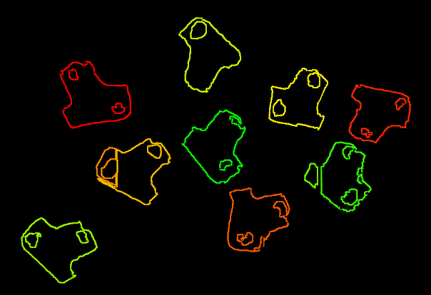
Figure 6. A sample result of Filter Out Point Clouds That Exceed the Limit
3D Matching
3D Matching is performed on the workpiece point clouds to obtain pick points after the point clouds are filtered.
A sample result of 3D Matching is shown in Figure 7.
Please see 3D Matching for details about this Procedure.
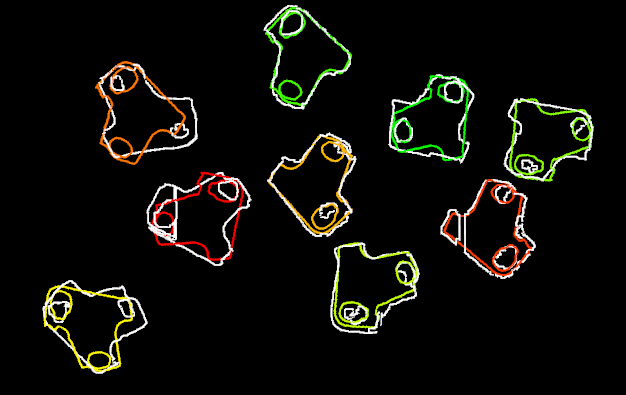
Figure 7. A sample result of 3D Matching
Pose Adjustment Collection
This Step is for adjusting the poses.
Please see Pose Editor for instructions on adjusting poses.
Map to Multi Pick Points
This Step takes a sorted pose list and maps them to a workpiece to provide different potential picking poses for the robot.
Please see Map to Multi Pick Points for details about this Step.