Piece Picking (without Bin)
This Typical Project applies to scenarios where objects are not placed in bins.
Mech-Vision Project Workflow
Since the target objects’ shapes differ greatly and no universally applicable model is available, grasp pose estimation is done by deep learning.
The workflow of a Piece Picking (without Bin) Typical Project is shown in Figure 1.
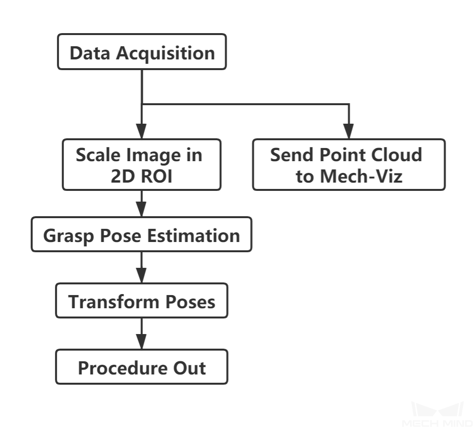
Figure 1. The Workflow of a Piece Picking (without Bin) Typical Project
Figure 2 is a screenshot of the graphical programming of the project.
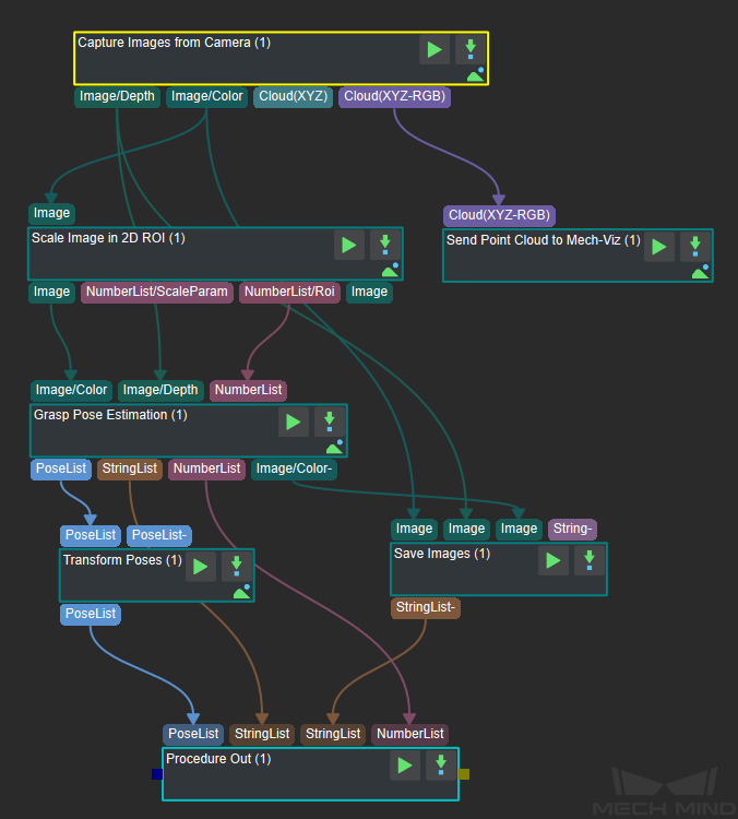
Figure 2. The graphical programming of a Piece Picking (without Bin) Typical Project
Steps and Procedures
A Procedure is a functional program block that consists of more than one Step.
Capture Images from Camera
This Step acquires the color image, depth map, and point cloud from the camera as the input data for subsequent vision calculations.
For details about this Step, please see Capture Images from Camera.
Scale Image in 2D ROI
This Step scales the ROI of the image to a designated size. The result of object pose estimation is largely dependent on the ROI and the scaling ratio; so the parameters of this Step must be adjusted for ideal pose estimation results.
For detailed instructions on adjusting the parameters of this Step, please see Deep Learning Deployment ROI Settings.
Grasp Pose Estimation
Because the target objects’ shapes may differ greatly, grasp pose estimation is done by deep learning.
Deep learning model file and configuration file, pose estimation model file, and overlap detection model file and configuration file obtained after deep learning model training should be loaded before running the Step.
Given the color image, depth image, ROI parameters and bin pose, the deep learning algorithm will generate the following:
The pose of the object’s pickable surface under the camera coordinate system (as shown in Figure 3).
The 3D dimensions of the pickable objects.
The suction cup labels corresponding to the object’s pickable surface.
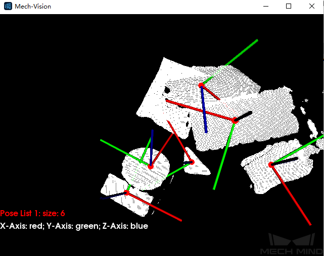
Figure 3. A sample result of grasp pose estimation
This Step can also display a color image with region labels in real-time. A color image displaying pickable regions labeled with suction cup sizes is shown in Figure 4. The type of label displayed can be changed in the Visualization section of the parameter panel.
Note
Enabling visualization will slow down the running of the project.
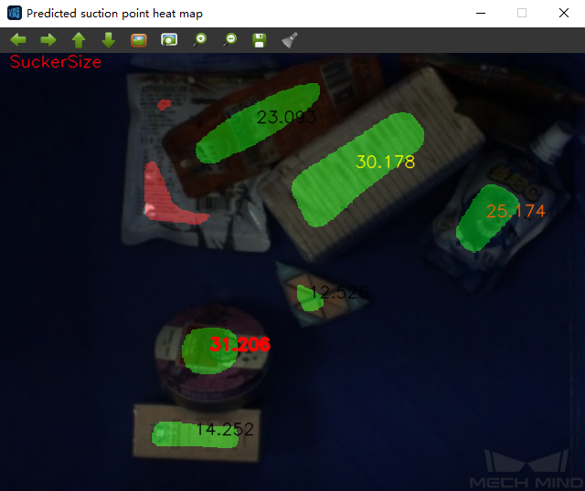
Figure 4. Visualization option: show suction cup size
Transform Poses & Procedure Out
Transform Poses transforms the list of poses from the camera coordinate system to the robot coordinate system. For details about Transform Poses, please see Transform Poses.
Then, Procedure Out sends the list of poses under the robot coordinate system to the server. Please see Procedure Out for details.