Large Non-Planar Workpiece Loading
Application Scenarios
The project is suitable for picking a small number of larger workpieces, usually when the workpieces have obvious features.
Mech-Vision Project Workflow
As the workpieces have obvious features, pose estimation can be easily done by matching between the object point cloud and a model point cloud. So, no deep learning is involved and the project can run fast. The workflow of a Typical Project for Large Non-Planar Workpiece is shown in Figure 1.
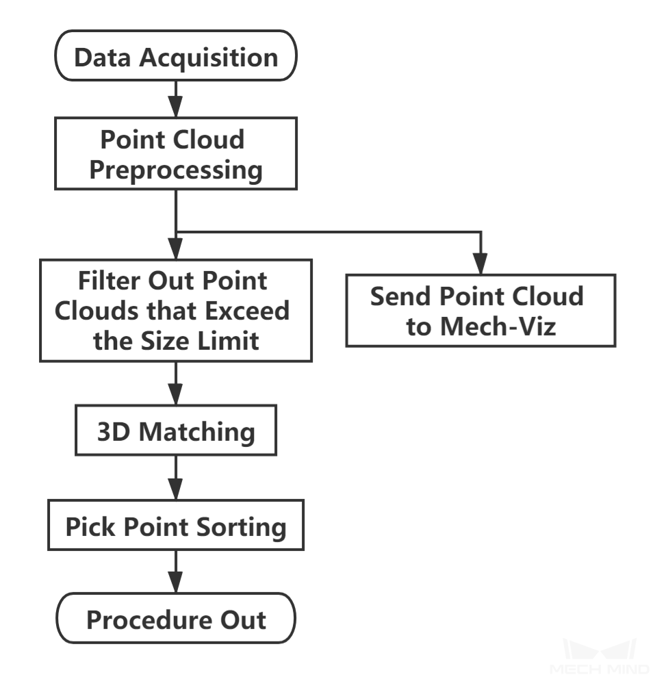
Figure 1. The workflow of a Typical Project for Large Non-Planar Workpiece
Figure 2 is a screenshot of the graphical programming of the project.
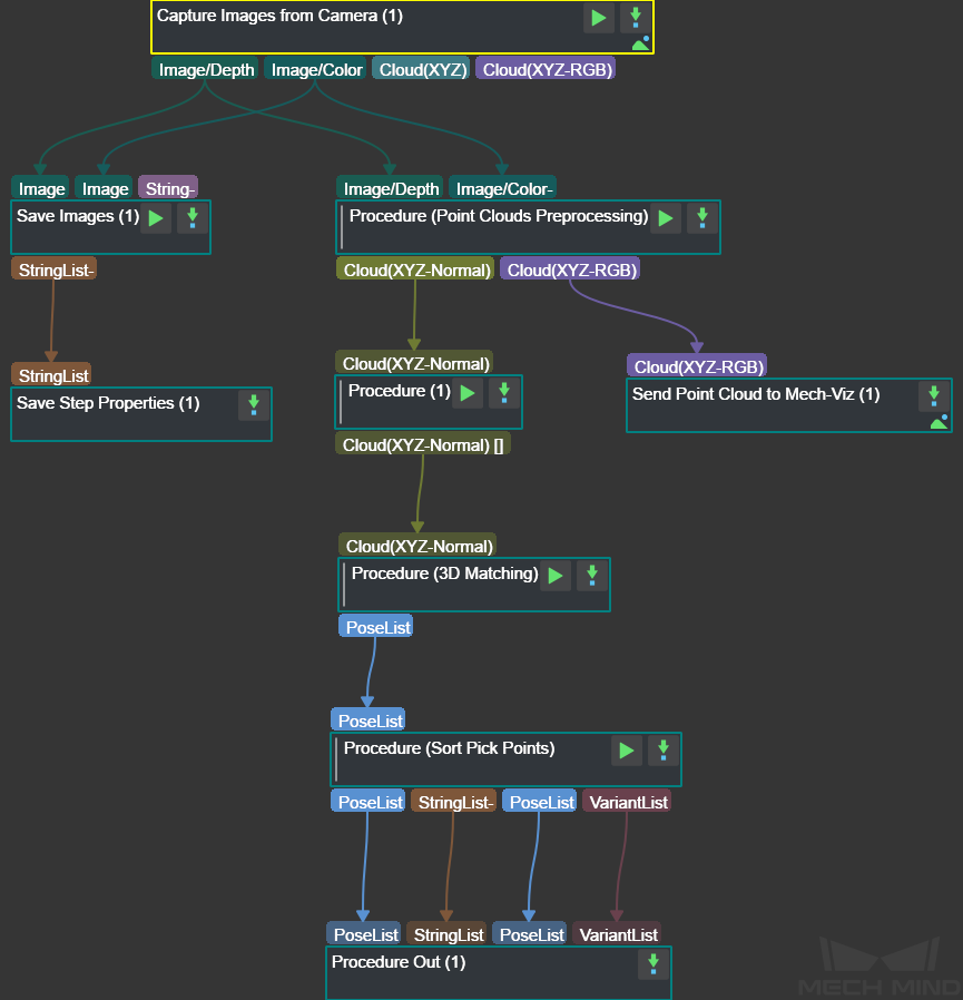
Figure 2. The graphical programming of a Typical Project for Large Non-Planar Workpiece
Steps and Procedures
A Procedure is a functional program block that consists of more than one Step.
Point Cloud Preprocessing
This Procedure facilitates and shortens the processing time for the subsequent calculations. Point Cloud Preprocessing generates a raw point cloud from the depth map and the color image, deletes the outliers, calculates the normals for the point cloud, and in the end extracts the part of the point cloud within the ROI.
For details about this Procedure, please see Point Cloud Preprocessing.
A sample result of Point Cloud Preprocessing is shown in Figure 3.
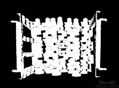
Figure 3. A sample result of Point Cloud Preprocessing
Filter Out Point Clouds That Exceed the Limit
This Procedure filters out point clouds that affect 3D matching to improve the accuracy of matching.
A sample result is shown in Figure 4.
Please see Filter Out Point Clouds That Exceed The Limit for the detailed description of the Procedure.
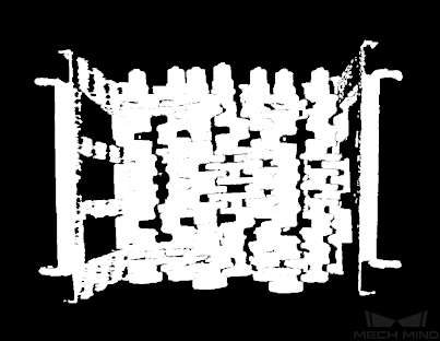
Figure 4. A sample result of Filter Out Point Clouds That Exceed the Limit
3D Matching
3D Matching is performed on the workpiece point cloud to obtain pick points after filtering the point cloud.
A sample result is shown in Figure 5. The colored parts of the point clouds match the model point cloud.
Please see 3D Matching for detailed information about this Procedure.
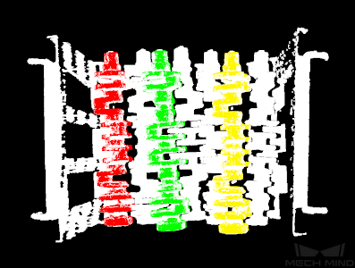
Figure 5. A sample result of 3D Matching
Pose Adjustment Collection
This Step is for adjusting the poses.
Please see Pose Editor for instructions on adjusting poses.
Map to Multi Pick Points
This Step takes a sorted pose list and maps them to a workpiece to provide different potential picking poses for the robot.
Please see Map to Multi Pick Points for details about this Step.