Piece Picking (with Bin)
This Typical Project is applicable to scenarios where objects are placed in bins.
Mech-Vision Project Workflow
The target objects are placed in a bin, so the picking task can be more easily completed by obtaining the relative positions of the target objects to the bin.
Therefore, the pose of the bin should be obtained based on the highest layer of the point cloud, i.e., the part of the point cloud for the bin’s upper edge.
Then the positions and grasp poses of the target objects should be obtained.
Since the target objects’ shapes differ greatly and no universally applicable model is available, grasp pose estimation is done by deep learning.
The workflow of a Piece Picking Typical Project is shown in Figure 1.
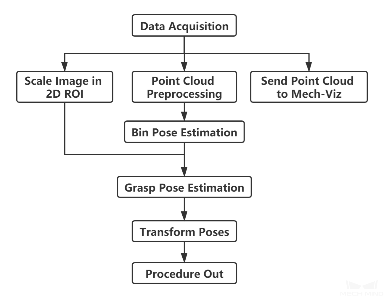
Figure 1. The workflow of a Piece Picking Typical Project
Figure 2 is a screenshot of the graphical programming of the project.
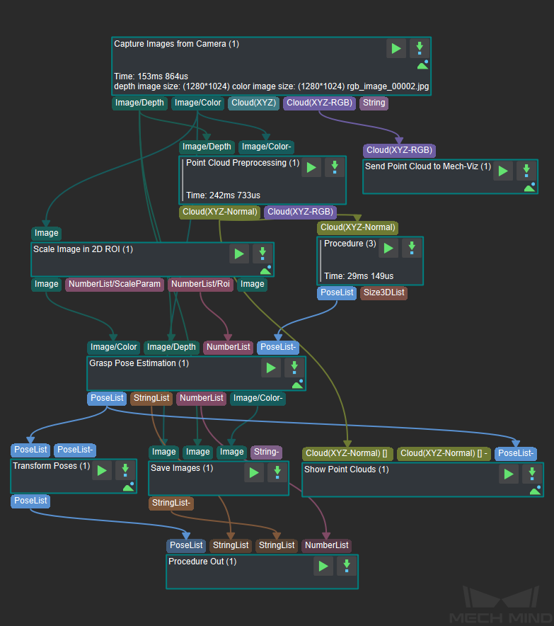
Figure 2. The graphical programming of a Piece Picking Typical Project
Steps and Procedures
A Procedure is a functional program block that consists of more than one Step.
Capture Images from Camera
This Step acquires the color image, depth map, and point cloud from the camera as the input data for subsequent vision calculations.
For details about this Step, please see Capture Images from Camera.
Point Cloud Preprocessing
This Procedure facilitates and shortens the processing time for the subsequent calculations. Point Cloud Preprocessing generates a raw point cloud from the depth map and the color image, deletes the outliers, calculates the normals for the point cloud, and in the end extracts the part of the point cloud within the ROI.
For details about this Procedure, please see Point Cloud Preprocessing.
A sample result of Point Cloud Preprocessing is shown in Figure 3.
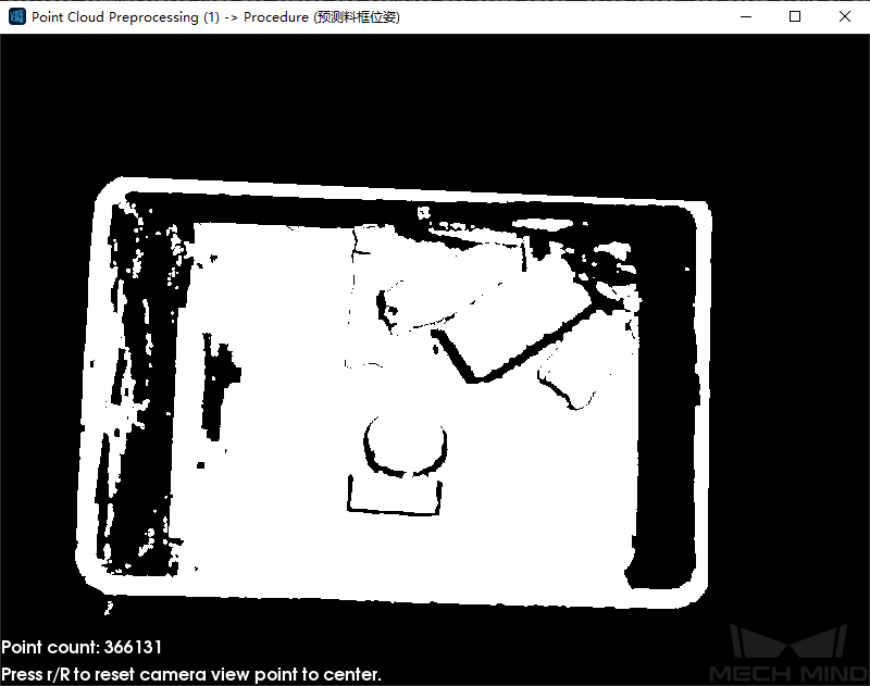
Figure 3. A sample result of Point Cloud Preprocessing
Scale Image in 2D ROI
This Step scales the ROI of the image to a designated size. The result of object pose estimation is largely dependent on the ROI and the scaling ratio; so the parameters of this Step must be adjusted for ideal pose estimation results.
For detailed instructions on adjusting the parameters of this Step, please see Deep Learning Deployment ROI Settings.
Bin Pose Estimation
Bin Pose Estimation is Procedure (3) in Figure 2.
This procedure estimates the pose of the bin by obtaining the point cloud of the bin’s upper edge. The point cloud is sampled to reduce its size and then clustered. Next, the point cloud of the highest layer, i.e., the point cloud part of the bin’s upper edge, is obtained, the pose and dimensions of the obtained point cloud calculated, and finally, the bin pose is output after flipping the Z-axis.
The bin pose is shown in Figure 4.
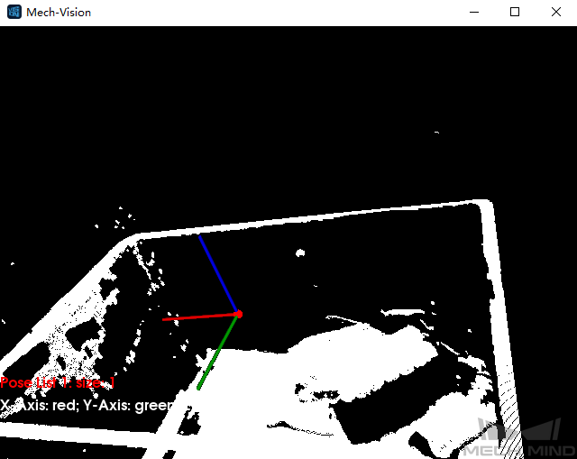
Figure 4. Bin Pose Estimation
Grasp Pose Estimation
Because the target objects’ shapes may differ greatly, grasp pose estimation is done by deep learning.
Deep learning model file and configuration file, pose estimation model file, and overlap detection model file and configuration file obtained after deep learning model training should be loaded before running the Step.
Given the color image, depth image, ROI parameters, and bin pose, the deep learning algorithm will generate the following:
The pose of an object’s pickable surface under the camera coordinate system (as shown in Figure 5).
The 3D dimensions of the pickable object.
The suction cup label corresponding to the object’s pickable surface.
Note
The purpose of inputting bin pose is to more accurately determine the position of an object relative to the bin.
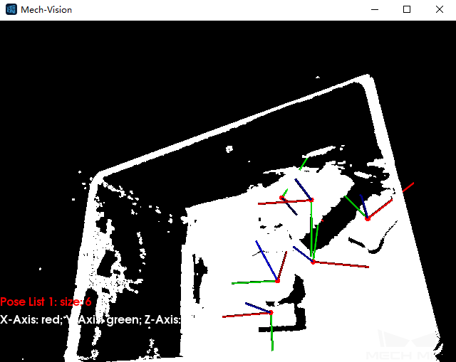
Figure 5. A sample result of Grasp Pose Estimation
This Step can also display a color image with region labels in real-time. A color image displaying pickable regions labeled with suction-cup sizes is shown in Figure 6. The type of label displayed can be changed in the Visualization section of parameters.
Note
Enabling visualization will slow down the running of the project.
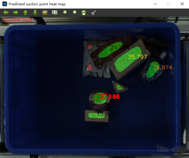
Figure 6. Visualization option: show suction cup size
Transform Poses & Procedure Out
Transform Poses transforms the list of poses from the camera coordinate system to the robot coordinate system. For details about Transform Poses, please see Transform Poses.
Then, Procedure Out sends the list of poses under the robot coordinate system to the server. For details about Procedure Out, please see Procedure Out.