Set Pick Points by Teaching
Pick Point Setting Usage Scene (Teaching Method)
For the project required high precision of pick point, the precision requires within 0.5mm.
The accuracy of TCP pose is not sufficient.
The pose of the workpieces are relatively consistent in the entire process, otherwise you need to use the multi-templates.
Operating Procedure of Setting Pick Points by Teaching
Method of making template
Release End effector, make sure the position of workpiece has not changed, take a photo at shooting point to have depth image and then generate point cloud template file(.ply) by corresponding Mech-Vision project.
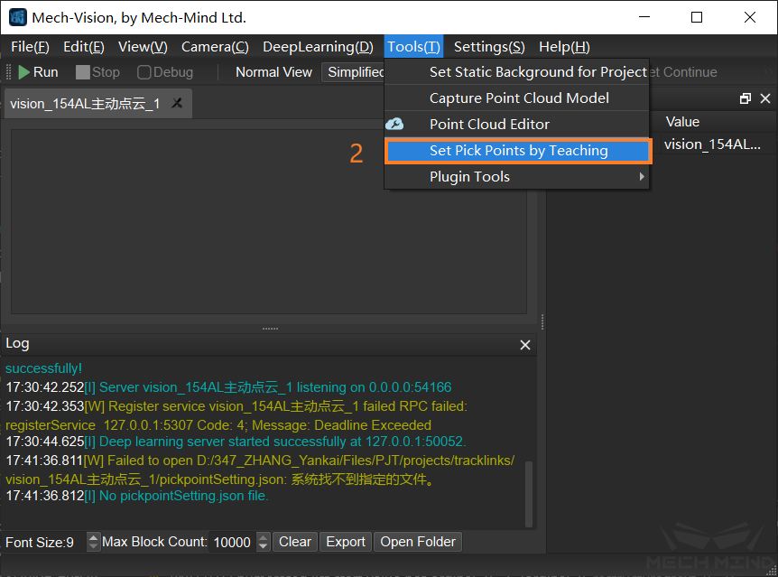
Mech-Vision->Tool(T)->Set Pick Points by Teaching
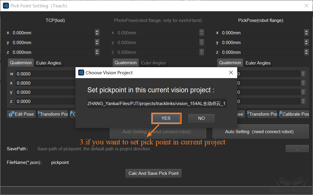
Select the corresponding project for pick point setting
Attention
After updating extrinsic parameters, pick point has to reset, otherwise it will cause errors
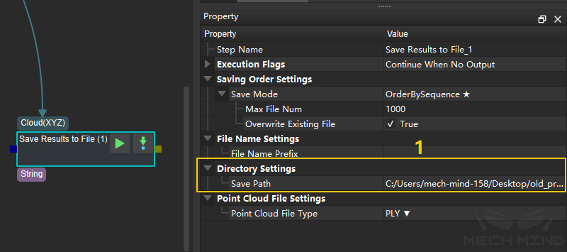
Select saving path
Attention
The default path for saving pick points template is the project directory.
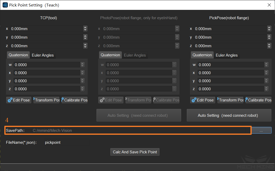
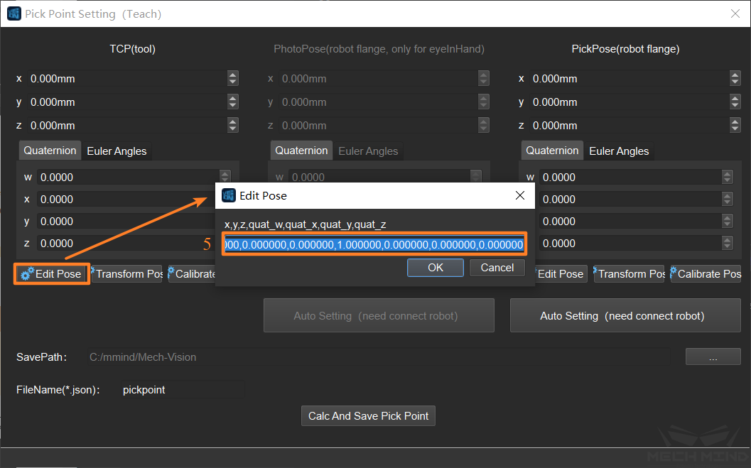
Set TCP Pose
Input TCP coordinate manually
Attention
If it doesn’t set TCP, the default tcp can be (0,0,0,1,0,0,0), which flange center point will be the pick point.
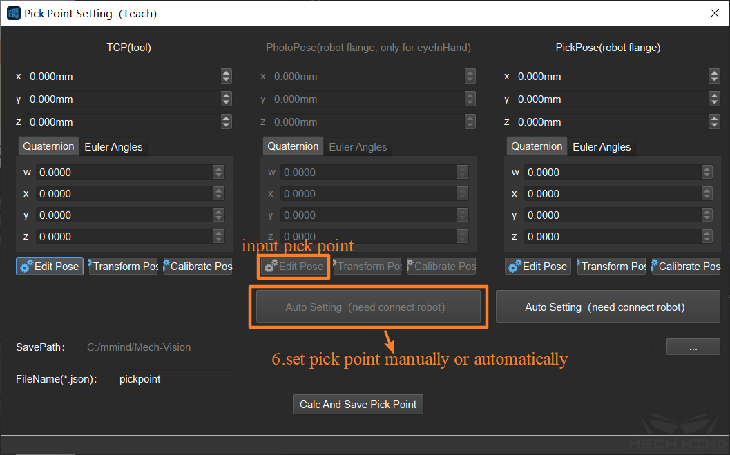
Set photo point (required only in the Eye In Hand situation)
Set photo point automatically: connect robot, move the robot to the photo point, click “Auto Setting” to set photo point and it will obtain the flange coordinate of the robot as the photo point automatically.
Set photo point manually: connect robot, move the robot to photo point, input flange center pose as photo point manually.
Attention
If the photo point is input manually, the subsequent pick point setting should also be input manually.
It has to input flange center pose, instead of TCP pose.
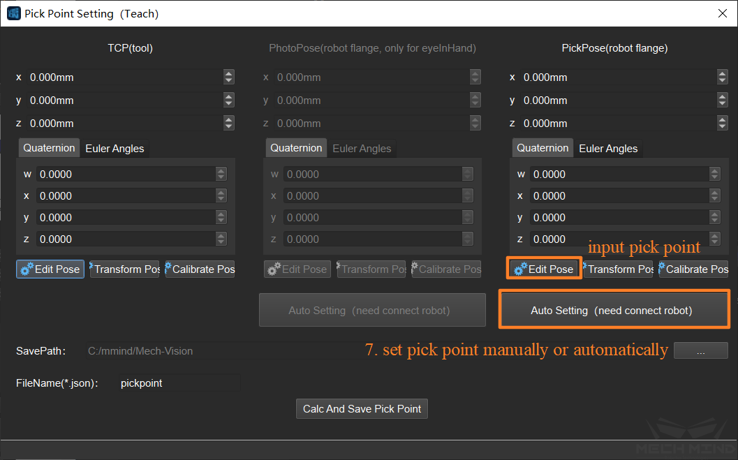
Set pick point
Set pick point automatically: connect robot, move the robot to the pick point, pick the object, click “Auto Setting” to set pick point.
Set pick point manually: connect the robot, move the robot to the pick point, pick the object, input robot flange center pose manually.
Attention
In order to make sure the pick point and photo point are under the same coordinate system, it has to ensure that the pose of object can not change before or after the end effector is enabled or release. You can clamped and release the object repeatedly, and set the pick point after the object is stable.
Click “Calc and Save Pick Point” (the file of pick point is saved under the path of corresponding project)
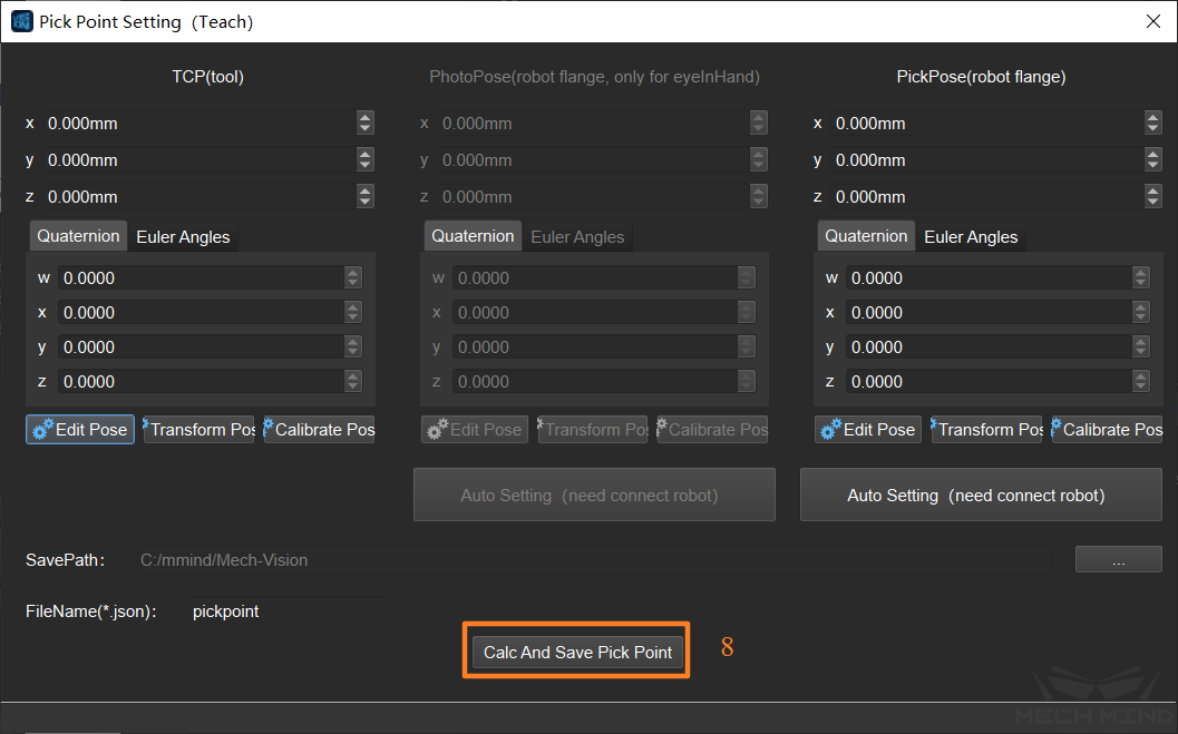
Attention
For the situation that the object is huge, which needs double cameras to recognize: the first step Capture Images from Camera is the secondry camera, and the second step Capture Images from Camera is the main camera. It has to run the whole Mech-Vision project before setting pick points.
Verify the correctness of pick point setting
Method 1: (Preferable)
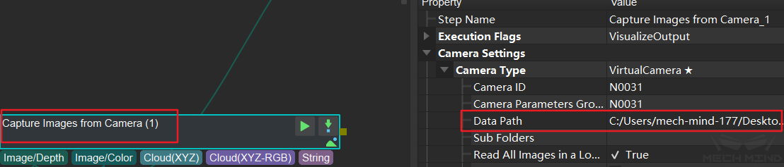
The directory where the RGB image and depth image for making template can be saved in the “dataPath” of step Capture Images from Camera.
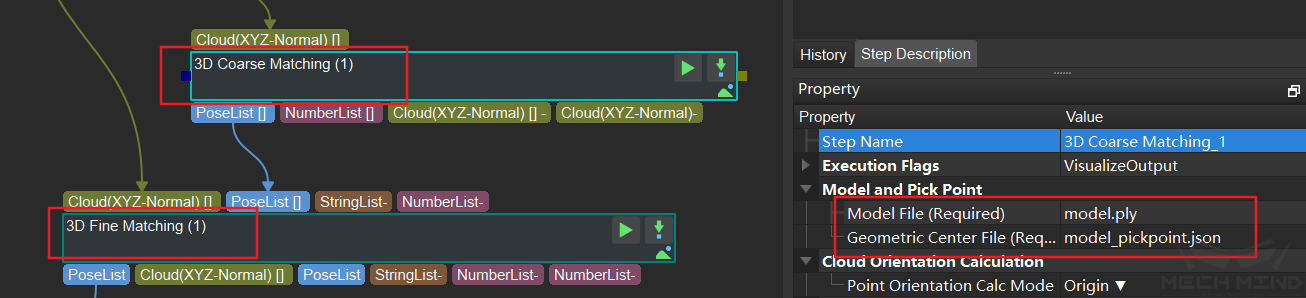
Set the template file and pick point file into step 3D Coarse Matching and 3D Fine Matching.
Connect the step Verify Pick Points after the step Transform Poses in Mech-Vision project, run and then achieve the verification environment of template self-matching scenario.
Attention
During this process, make sure the pose of object does not changed
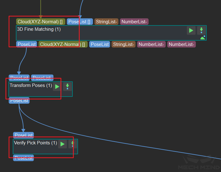
The specific meaning of the pose output from the step Verify Pick Points is the difference between the pick point pose set by user and the pick point pose output from Mech-Vision project. As the figure shown below, observe “TextOutput” of the step Verify Pick Points , the difference along Y axis of pick point pose is 1.4mm, the error is relatively greater.

Attention
It has to make sure that the error of 3D Fine Matching is very small, otherwise the output error of Verify Pick Points step is bigger, because it is consisted of matching error and pick point error.
Method 2
Load new template and pick points files, run the corresponding project in Mech-Vision. Use Mech-Viz to control the robot to pick the object which is used to set pick point. If it can accurately pick the object, that proves the pick points is set correctly.
Attention
If the setting of pick point has some problems, it may cause collision. If you want to use this method, be cautious to operate robot.