Parameter Compensation
Long-term operation of the robot and camera may cause slight changes in the intrinsic and extrinsic parameters of the camera, which will affect the accuracy of grasping. If it is not possible to calibrate the camera on site, the parameters compensation method can be used to correct the intrinsic and extrinsic parameters of the camera.
The principle of parameters compensation is similar to Hand-Eye Calibration Guide, and it can be regarded as a lighter and faster calibration. As a result, its accuracy is not as high as the camera calibration. When there are serious camera positioning problems (according to the requirements of different tasks), it is recommended to recalibrate.
The parameters compensation tool is under . Click Parameters Compensation, there will be a dialog box as shown in the figure below.
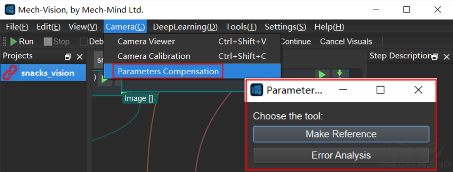
Make Reference is to detect the markers and estimate their poses in camera coordinates through each observation. Compensation is obtained by comparing the difference between the baseline (initial) observation poses of the markers in the scene and the subsequent observation poses.
Error Analysis is a data visualization analysis of the results of parameters compensation.
Procedure of Parameters Compensation
It is required to add a process of detecting markers and compensating parameters after the normal field tasks, and the markers need to be fixed on site. In terms of project, it is necessary to add some Skills to the original Mech-Viz project and add some Mech-Vision projects. The Skills and projects that need to be added is shown in the figure below.
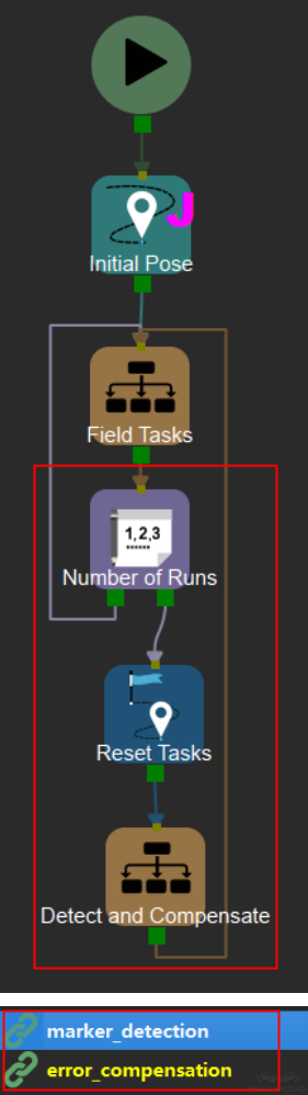
Compensation is not required every time a normal project is carried out, so a Counter and a Reset Task are added to set a value and perform compensation when the number of times of normal project operation reaches this value.
The added content is generated by make_reference in Mech-Vision. The usage of this tool will be introduced below.
Make Reference
Set Camera Exposure Parameters
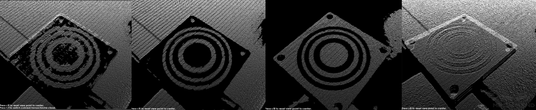
Under the condition of meeting the original project requirements, adjust the 3D exposure parameters in Mech-Eye Viewer until the white area on the surface of the markers has point cloud. The picture below ranges from poor to good. The image on the far left is the worst, while the image on the far right is the best.
Make sure that the markers are within the best field of view of the Mech-Eye camera to ensure smooth point clouds on the surface of the markers. If it cannot be guaranteed due to special reasons, priority should be given to ensuring the smoothness of the point cloud near the key points of the marker (center of a circle, corner points of a square).
Connect to Camera
Click Parameters Compensation and select Make Reference. The interface is shown below.
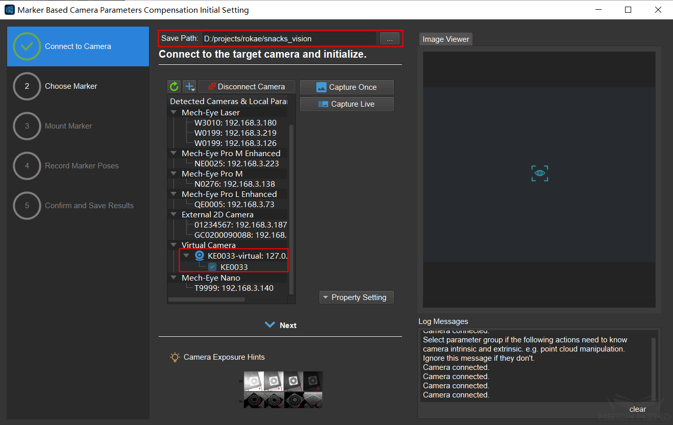
User needs to set the save path, connect to the camera, and select the existing camera extrinsic parameters group. Click Capture Once after connecting to confirm that camera connection is correct. Then click Next.
Choose Marker
At present, there are not many options for markers, just choose marker type, camera mounting method, marker mounting method and use default value for other parameters. More parameters and types of markers will be added later to suit different scenarios. It is recommended to use CCTag or STag. In this article, the camera mounting method is EIH, the marker type is CCTag, and the marker mounting method is marker to hand . The detailed settings are shown in the figure below. Click Confirm and Next to the next step.
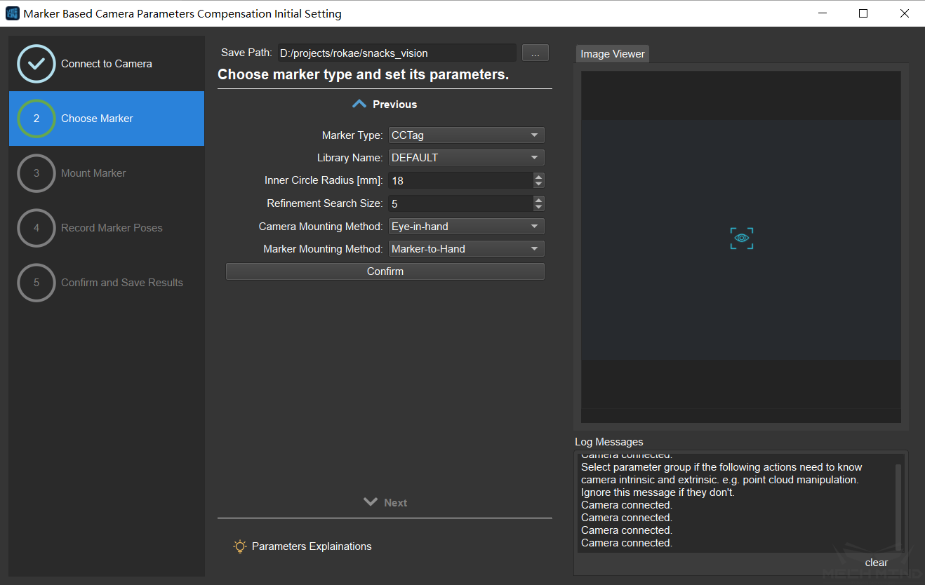
Note
If the camera mounting method is ETH, marker mounting method needs to be marker in hand.
Mount Marker
At this step, the camera will continuously capture images, and the real-time position of the markers can be seen from the image viewer on the right.
The placement rules of the markers are as follows:
Mount the marker at a suitable position in the work area or on the robot arm. Make sure that the relative position of the marker and the fixed object (ground, robotic arm, etc.) remains unchanged.
If marker is placed in the work area, it is recommended to use multiple markers with different numbers (ID), and they should be scattered as much as possible in the camera’s field of view.
If multiple markers are used, try to ensure that any three markers are not in a straight line.
After placing the marker, click Capture Once. It will take a few seconds for the software to calculate the estimated position. As shown below.
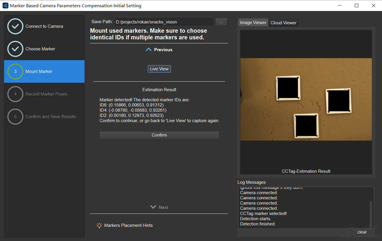
After confirming that the result is correct, click Confirm and Next.
Record Marker Poses
First, record the robot’s initial observation position (i.e. flange pose) and the marker pose at this time
Click the Save Current Flange Pose and Estimated Marker Poses button. After completion, it will display “Observation #1”. As shown below.
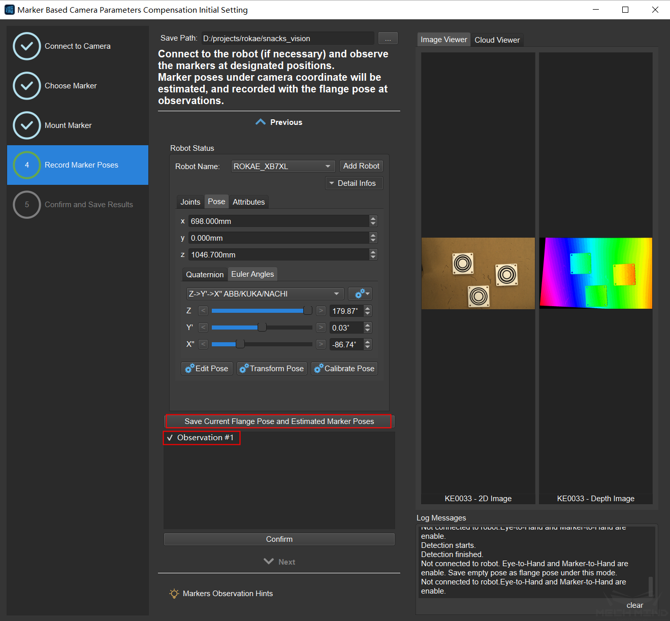
Move the robot to the expected observation position through Mech-Viz or the robot teach pendant and click “Save Current Flange Pose and Estimated Marker Poses” again, one more observation result will be displayed.
Add more observation results and then check whether each result meets the requirements. If there are observation results that do not meet the requirements, uncheck them and they will be discarded. Then click Confirm and Next.
Confirm and Save Results
The interface is shown in the figure below, and user can modify the name of the output file. Then click Save.
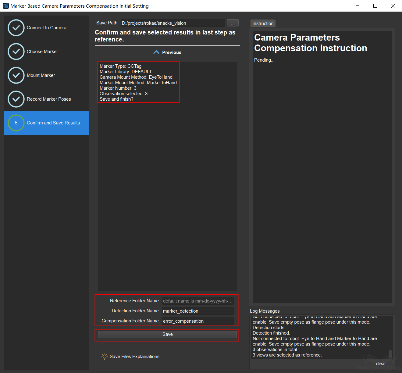
Three items are saved:
Parameters compensation folder: ParamsCompensation.
Each reference will be saved in a folder named in the form of “date-trial”. There can be multiple reference for the same project, which can be selected and used according to requirements.
flange_*.json records a single flange pose, which is used to send to the robot motion trajectory points later using Read Poses from File Step.
flanges.json records the flange poses of all observation positions. This file is planned to be used to send motion trajectory points to the robot through other Steps, but it is not used at present.
reference.json records all the information and observation results related to parameters compensation. It is used with Validate and Calc Parameter Compensation Step to compare observation results and calculate compensation.
observation_*.json records the estimated results of subsequent observations.
offset.json records the compensation data generated by Validate and Calc Parameter Compensation Step, which is used to compensate the pick points later using Read Poses from File Step.
Attention
The pick points to be compensated must be based on the camera coordinate system. If they are in the robot coordinate system, coordinate transformation should be carried out before compensation.
Mech-Vision project————Marker detection: marker_detection.
This Mech-Vision project uses Mech-Viz to call the vision service to detect the position of the marker, and save the estimated result of the position of the detected marker to the file observation_*.json.
Mech-Vision Project————Error analysis: error_compensation.
This Mech-Vision project uses Mech-Viz to call the vision service to calculate the compensation. By reading the marker pose in the observation_*.json file, comparing it with the initial marker pose and calculating, the compensation is obtained and saved in the offset.json file.
Use the Generated Projects and Files for Error Compensation
Mech-Vision Projects
In addition to the original project, the two generated projects, marker_detection and error_compensation, need to be added.
The marker_detection project needs to set the camera IP and camera parameters group, and the path to save the images.
In the Detect Fiducial Markers Step, user needs to set the parameters compensation folder ParamsCompensation and the reference target (i.e. the folder named in the form of “date-trial” in the parameter compensation folder).
Similar to :guilabel: Parameters Compensation Step, the error_compensation project also needs to set the parameter compensation folder ParamsCompensation and reference target.
Mech-Viz Project
The Mech-Viz project can be set as shown in the figure below. First place the original project in the Field Task mission.
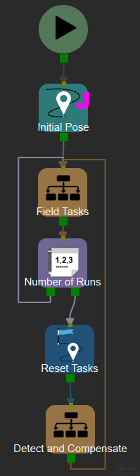
Then add counter, reset tasks, and detect and compensate.
The counter is set according to the actual situation. (That is, how many times the field task runs before compensate once)
Select the counter as the task to be reset for the Reset Tasks Skill.
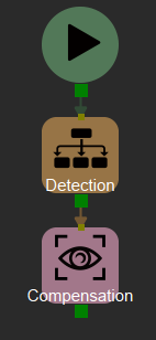
The content of detect and compensate mission is shown in the figure below. There are two modules of detection and compensation.
The content of detection mission is shown in the figure below.
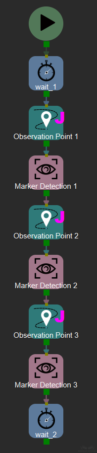
Poses at the observation points (Move Skill) are set as the pose at the initial observation point. Pose is recorded in the flange_*.json file mentioned above. The number of observation points depends on the number of markers.
Visual_look Skill needs to call the marker_detection vision service. The number of visual_look Skills also depends on the number of markers.
Compensation (visual_look Skill) needs to call the error_compensation vision service.
Now, run the Mech-Viz project to perform camera parameters compensation in the project.
Error Analysis
Error analysis is to visualize the generated result of camera parameters compensation, and the trend and distribution of the error can be seen through the chart. Select Error Analysis in the parameters compensation tool to enter the error analysis page. As shown below.
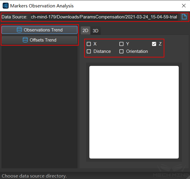
First, select data source, which is the folder named in the form of “date-trial”.
Observations Trend: Observe the trend of the errors of the markers’ poses. The data is from the observation_*.json file in the folder.
Offsets Trend: The trend of the compensation values. The data is from the offsets.json file.