Process for Project Deployment
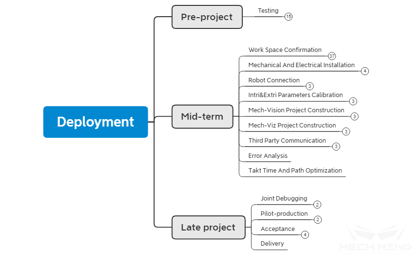
The process mainly includes early phase, middle phase and late phase.
The purpose of the early phase is to test whether the target object meets the requirements of Mech-Mind Vision System, and whether it can be detected, collect relevant data;
The main purpose of debugging in the middle phase is to enable the robot to complete the established process and meet the required takt time of the project;
The late phase is the project implementation phase, mainly for joint debug, to cooperate with factory production, to meet the production requirements of the factory, and to find and solve small problems during the long-term trial production process.
The project deployment process is shown in the following figure.
Process for project deployment
Early phase
Test
Point cloud test
Key point The key point is the features such as round holes, special surfaces, object edges, etc. which is easy to be identified on a workpiece.
Parameter adjustment After the key point is clarified, when performing a point cloud test, the camera parameters can be adjusted according to the key point so that the details of the point cloud at the key location become obvious. For details about the adjustment on the point cloud of Mech-Eye Viewer, please see the section Parameters adjusting of Parameter Adjustment.
Simple matching Some simple projects can be judged directly by experience. For some complex workpieces (no obvious features or complex features), a simple Mech-Vision project can be set up in the laboratory to check whether the matching can be performed and whether the expected effect can be achieved when the matching time is ignored. It is also possible to test the accuracy of the match. For different types of identification projects, please refer to Vision Typical Typical Applications.
Build a Demo You can use the existing robots, cameras and end effector (pointers) in the laboratory to build a simple Demo ( see How to build a Demo ) so that show customers more practical results. The main purpose is to directly show the recognition effect and robot reachability.
Data collection
Collection requirement For projects that require the function of deep learning, data collection may be required. For each project, it has different collection requirements, such as item placement, quantity of collection, light quality, etc.
Hint
During data collection, the project engineer need to follow the Collection standard from the R&D department, and supplements the amount of data if necessary.
Environment control Before the data collection, controlling on the collection environment is required, if the environment is changing or the data collected in poor environment, it will affect the training effect of deep learning model. In the data collection, camera parameters, lighting environment and field of view are mainly adjusted. For details, please refer to Lighting control of Illumination control
Upload data When the data is collected in accordance with the Collection standard , the content can be packaged and uploaded, and the data collected by different batches of different cameras is required to be indicated.
Hint
The data contains:
Raw data
Intrinsic parameter of camera
Hardware inspection
The hardware inspection mainly includes the checking of IPC and cameras used in Mech-Mind Vision System.
Hint
IPC will be installed after initial purchase, refers to Software installation and configuration . before the shipment, the software of IPC will be checked, the checking mainly includes whether the system environment is up-to-date, whether it is installed successfully, etc.
After shipment from our plant, the camera intrinsic parameter check will be performed. The intrinsic parameters may be changed during the long-term storage and transportation. Therefore, it is necessary to check the camera intrinsic parameters before the project is implemented.
Middle phase
On-site situation confirmation
Project goal confirmation
Process flow For the deployment of a project, the most important goals are takt time and project goal. The takt time is efficiency and is the time it takes for a robot to complete a set of process flow, it may have different strategies and designs for different project requirements. The project goal is the content that needs to be completed for the project deployment, such as loading, depalletizing, etc., and more detailed content is required, such as grasping or placing method, pose, overall accuracy, etc.
Hint
Familiar with the project process is helpful to have a deep understanding of the overall situation, and you can adopt different scheme strategies for different project processes.
Time nodes Project time nodes is the time corresponding to the start, deployment, joint debug, trial production, and delivery of the project.
Hint
Different projects have different time nodes, so a good understanding of the time node will make arrangements for the work reasonable. For demonstration projects, there is no process of joint debug, trial production, and delivery, therefore there will be a big difference in the arrangement of the time nodes.
Control method There are two main control methods currently used in Mech-Mind Vision System. One is Mech-Viz main control, the other is Robot main control.
Hint
The project controlled by Mech-Viz is a regular project, it is required to be processed step by step according to the deployment process;
For the project controlled by robot, vision points are sent to robot mainly via Mech_Adpater. When receiving the vision pose, the robot analyzes and performs the operation. It is not necessary to build a Mech-Viz project for such project after completing extrinsic parameter calibration and setting up a Vision project.
Robot confirmation
Whether it works Check whether the robot can work properly. The main contents that can be followings:
Check if the relevant power cable of the robot is connected properly and is not damaged
Check if the robot control cabinet is working properly
Check if the teach pendant is working properly
Check if the I/O board of robot’s control cabinet is in good condition
Check the dryness inside the robot control cabinet
Hardware and software configuration The checklist of software and hardware configuration mainly includes Package permissions and version and I/O board. Wherein, the software package permissions and versions are required to be confirmed. The main reason is that Mech-Mind’s robot adaptation system is adapted to a specific software version (mainstream). The later or earlier version may cause communication errors and make the robot unable to control. Therefore it is necessary to confirm the software version of the robot to ensure that the version is appropriate, and upgrade or downgrade it if necessary. The I/O board also is required to be confirmed. Some robots support multiple I/O boards and is required to be reasonably configured to be able to be controlled in Mech-Viz.
Hint
For example, YASKAWA robots may transmit different signals when connecting different I/O boards.
I/O signal confirmation I/O signal confirmation indicates confirming the I/O signal that communicates with Mech-Mind Vision System. Such as the workpiece in-position signal, the signals for the end effector opening and closing, etc.
Tip
In the case of fewer I/O signals, it can be directly recorded via Mech-Viz;
If more I/O signals are required in the project, list the I/O table.
Method for anchoring The anchoring method refers to the fixing method of the robot base. At present, the main fixing methods include fixing by the chemical bolting and fixing on a movable platform. For the fixing method of the robot and the possible problems, please refer to the Method for Fixing .
Null point After the robot has not been used for a long time or after a collision, it is necessary to confirm the null point of the robot to prevent the losing of robot’s null point or the battery for data storage being out of power. For the method of checking the null point, please refer to Null point Null point .
Manually controlled Robot The purpose of the controlling robot manually is to determine whether the robot can reach the working position.
Tip
In Eye to Hand mode, control the robot to the farthest distance from the robot to confirm whether the robot is reachable and not at the limit on the soft limit of the robot;
In Eye in Hand mode, a manually controlled robot and a mobile robot are required to respectively confirm whether the camera’s shooting position has visual field interference, whether the camera will interfere with the robot, and whether the robot can reach the farthest workpiece position.
Layout confirmation
The main content of the layout confirmation is to determine whether the position of robot, camera layout, picking box (material rack), etc. are consistent with the drawing, whether the robot’s motion will be affected by camera bracket, protective fence, separation wall, etc. and cause possible robot trajectory error or unnecessary collision.
End effector confirmation
Initially confirm whether the end effector of the robot is suitable, and check whether during the movement the end effector will break the signal cable or interference with the robot will occur during the move of the end effector. Meanwhile, it is necessary to confirm whether the calibration will be affected after the end effector is mounted.
Hint
If the end effector is too long, during the calibration process, the robot cannot be calibrated at a deeper position, which may affect the extrinsic parameter results, and may also affect the camera field of view (cannot see the full calibration board).
Confirmation of electrical connection
Power supply For power supply it needs to confirm whether the power supply is stable. In some factories due to design defects, the provided 380V and 220V power is not stable, especially 220V. Therefore, the voltage is required to be determined before connecting the camera. If it is unstable, an additional voltage regulator must be connected to the camera to ensure that the camera’s power supply is stable. At the same time, in a typical Mech-Mind vision system, the equipment using a 3-pin plug include IPC, monitor, router, camera, sometimes two cameras or robots may be used at the same time by a voltage of 220V for power.
Tip
When using a power strip, prepare one with at least 6 outlets. Finally, check whether the overall layout of the workstation is safe and the cables are not directly exposed. Use wire arranging groove and wire trough if necessary. For more information about the power supply, please refer to Power control .
Air supply The inspection of air is mainly focused on pressure stability and pressure level. Wherein, the stable air pressure mainly determines whether the project can be carried out stably. In some projects, an air pump may be used. When an air pump is used by several places, the air pressure may be unstable, which may cause the situation that the end effector is closed or the suction power of the suction nozzle may be small or large. In addition, for larger suction cups and pneumatic end effector items, additional confirmation of air pressure is required. The air pressure determines the suction power of the suction cup, which is a guarantee of stability when sucking some heavy objects.
Mechanical and electrical mounting
Mounting camera and camera supporting bracket When mounting the camera and camera supporting bracket, it is necessary to determine the mounting position and direction for the camera according to the drawings. During mounting, the camera and camera support is required to be fixed. For details, please see Mounting the Camera.
Mounting flange and end effector Mount the flange and end effector correctly according to the drawings. Before mounting, it is necessary to determine the mounting direction for some axisymmetric end effectors to prevent the repeated work.
Electrical connection Connect and properly configure the sensors needed in the deployment project. When power on, test the hardware devices of the project such as cameras, IPC, monitors, routers and other devices.
Hint
Connect the air pipe required on the end effector of the robot. Ensure that the end effector works properly and the air pipe is in the proper length, and will not be unsightly because it is too short or torn by the robot.
Marking and tidying cables For the projects that use a lot of wires, it is necessary to use labels to mark the wires. It is mainly marked on commonly used cables (Ethernet cables, power cables, etc.) and I/O signal lines (positive and negative anodes, sensors, etc.).
Tip
If the camera cables and lighting cables used in the project are too long, arrange these wires after the layout is basically completed, use cable ties to bundle these wires and put them into the cable organizer;
The signal cables on the robot are required to be fixed closely with the robot body or the end effector to prevent it from being torn or hung.
Robot connection
Burn the Robot program Mech-Mind has different adaptation programs for different robots. In order for the robot to be controlled by Mech-Viz, the adaptation program is required to be burned into the robot. Different robots operate differently, please refer to Robot Integrations for details.
Connect Robot via Mech-Center Before using the Mech-Center to connect the robot, it is necessary to perform different operations on the robot so that the robot is in the signal receiving mode. Refer to Robot Integrations. When connecting to the robot via Mech-Center for the first time, user needs to click Deployment Settings and enter Robot Server page to set Robot Server Path and Host Address. It is also necessary to check Autoload Current Project in Mech-Viz. Then user can create connection to robot by clicking Connect Robot in Mech-Center.
Check kinematic parameters After connecting and synchronizing the robot with the Mech-Center, open Mech-Viz to check the kinematic parameters of the robot. The purpose of checking kinematic parameters is mainly to obtain correct joint angle and to keep the robot pose consistent.
Calibration for intrinsic and extrinsic parameters
Camera parameter adjustment In the on-site working environment, it is necessary to adjust the camera parameters, so that the plane of the calibration board can be clearly observed in Mech-Eye Viewer. During the adjustment process, if no best result can be obtained, please refer to Parameter Adjustment.
Hint
The camera parameters which is used for extrinsic parameters calibration are often different from the parameters used for identification. When the extrinsic parameter calibration is completed, it is required to adjust the camera parameters again to obtain a clear point cloud of the workpiece.
Check intrinsic parameters Please refer to Check Camera Intrinsic Parameters.
Calibration for extrinsic parameters Please refer to Hand-Eye Calibration Guide for the calibration of the camera extrinsic parameter.
Build a Mech-Vision project
The building of a Mech-Vision project is determined by the features of the object (round holes, planes, protrusions, etc.) and point cloud effects. For the building of Mech-Vision project, please refer to Typical Applications. When the basic project is set up, modify the parameters to achieve different recognition effects according to the different requirements of the project. For details, please refer to Step User Guide to Steps . If any errors occur in the process of project building, refer to FAQ .
Build a Mech-Viz project
Build a Mech-Viz project according to the customer requirements, the robot motion and I/O signals. For details, please see Instructions and Skills.
Third party communications
If the third party communication is required, it is necessary to determine communication method and communicate the preliminary ** communication protocol** as soon as possible. Prepare and test the Adapter in advance to ensure that the two parties can communicate normally and not affect the project progress because of the communication connection.
Error control
For error analysis, please refer to Error Error control .
Route optimization
For route optimization, please refer to route Takt Time and Path Optimization .
Late phase
Joint debug
In the joint debug phase, it is necessary to cooperate with the entire production line for testing. For example: Using a conveyor belt to move the material instead of manual handling, the robot can complete the grasping of one or more objects in the box under the supervision.
During the coordination phase, errors may occur during the troubleshooting process, such as failure to keep up with the takt time and the signal of in place is not detected, etc.
Tip
In order to reduce the tedious operation procedures, integrate multiple programs and start them with one click in HMI, which reduces the complexity of the software and the learning cost, and improves ease of use.
Trial production (Accompany production)
The main principles in the trial production phase are No major issues, Solve minor issues . In the trial production phase, all the requirements determined in the early stage of the project should have been met, and no major problems should occur during the production process (robot stop, recognition errors, etc.). Solve all minor problems, such as the unsatisfactory wire layout on the site, no labels, tiny adjustments on the point position, etc.
Handover acceptance
Customer training, operation manual, etc. Train the customers who use the project, including basic software operation, camera calibration, problem checking and other functions. Meantime, train the customers with TeamViewer and Simple troubleshooting to facilitate later maintenance. Create project operation manuals, and help customers to follow the operation manuals to perform the camera shooting and robot operation.
Handover checklist Create Handover checklist , determine the delivery content, confirm and take away Extra purchased items .
Software and project backup Perform Software and project backup, determine the Version of currently used Mech-Viz and Mech-Vision and backup project and original image used on-site , to facilitate later debug, maintenance and learning share.
Project summary Make a reasonable and appropriate Project summary , record the problems encountered during the project and related solutions and less commonly used techniques to help other engineers to learn and improve overall debug and deployment level.