Takt Time and Path Optimization
- Takt time in Production:
Takt time refers to the required time to process one workpiece, that is, the requirement of the user defined annual output on the efficiency of the robot workstation.
At present, most projects have requirements for takt time, and some projects have extremely high requirements for takt time (within 4 or 5 seconds). For projects with high takt time requirements, after the workstation can complete the entire operation process, Mech-Mind Software Suite will optimize the takt time via the vision algorithm optimization and robot route optimization. The takt time includes the camera shooting time, Mech-Vision processing time and the time from Mech-Viz planning to the robot complete the process. Therefore, the entire process for takt time and route optimization can divided into the above three parts, as shown in the following figure.
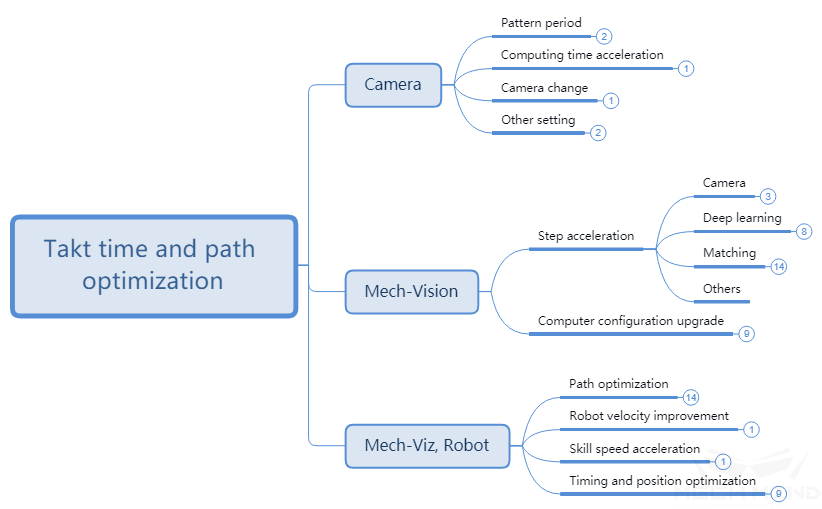
Figure 1 The overall concept for route and takt time optimization
Mech-Eye Viewer
Projection Time
2D/3D Exposure Parameters (HDR)
- HDR:
The HDR function is a technology that combines photos by shooting objects through different exposure cycles to improve the range of light and dark in photos, and enhance the details of point clouds.
When using Mech-Eye Viewer software, in some usage scenarios: such as recognizing complex structures of metal parts, objects with more details, etc., you can switch the 2D exposure mode and use two to three sets of different 3D exposure times to take pictures. Get more information. At the same time, it should be noted that in more scenes, such as cardboard boxes, flattened workpieces, etc., it will save half of the projection time without HDR. As shown below.
For the adjustment of 2D/3D exposure parameters, please refer to Mech-Eye Viewer - Parameter Adjustment.
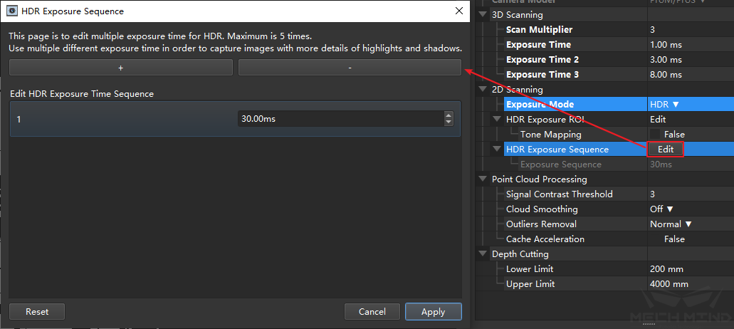
Figure 2 Modification on projection time
Update
Using the latest version of Mech-Eye Viewer software and updating the camera firmware version at the same time can increase the speed of generating depth maps and point cloud maps, and improve the speed of photographing.
Camera Replacement
In Mech-Mind’s camera appropriate, such as the Deep series of cameras, due to the large field of view, it is necessary to use two optical machines to project separately, and then synthesize the obtained point clouds. Therefore, the projection time will be twice as long as Pro M and Pro S series cameras under normal conditions. After determining the working scope of the scene, using a suitable camera can improve the speed of taking pictures.
Deep ROI
The depth ROI is the divided area in the camera’s field of view, it is used to reduce the amount of data to be processed by the camera. The depth ROI can be set in the XY direction and the depth limitation respectively to reduce the number of point clouds as a whole.
The ROI setting in the XY direction is shown in the figure below. The ROI range is determined by drawing a frame after entering.
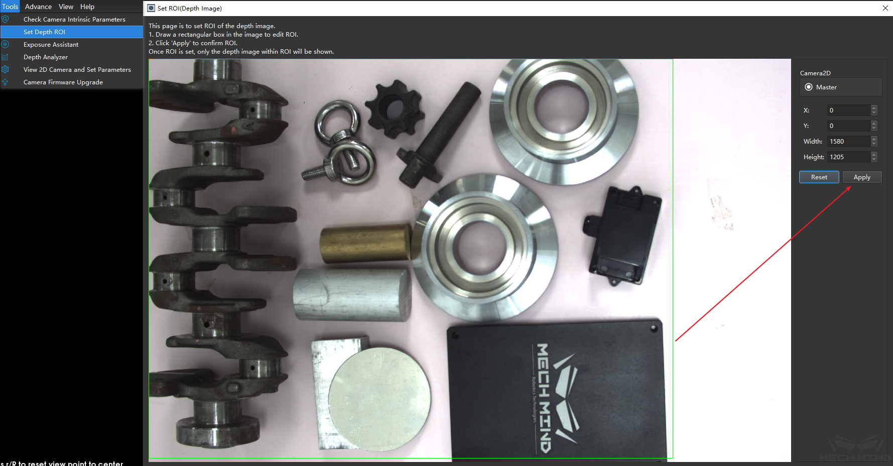
Figure 3 Set the depth ROI (XY)
The limitation in the Z direction are required to be set in the camera parameters. Setting the minimum and maximum depths separately can effectively reduce the number of point clouds. The units in the figure is mm.
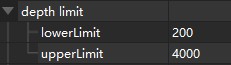
Figure 4 Setting the depth ROI (Z)
Mech-Vision
Step Acceleration
Capture Images from Camera
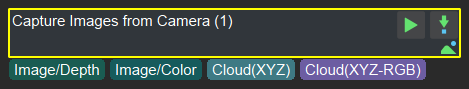
Figure 5 Get images from the camera
Capture Images from Camera is the most important step in Mech-Vision project, and it also takes up about 40% time in most of projects. The time consumed by Capture Images from Camera can be mainly optimized by the above method. Meanwhile, the function of Capture Images from Camera can also be split, since the camera collects RGB images and depth images and combines them to generate point cloud images. In some projects, point cloud and RGB images may need to be processed respectively at the same time, such as the project with deep learning, they can be processed respectively. As shown in the figure below, since the project is calculated in parallel, more time cab be saved.
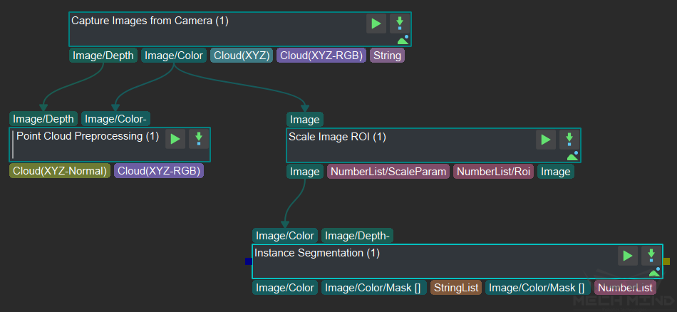
Figure 6 Parallel computing of deep learning and point cloud processing
Point Cloud Processing
In actual projects, the point cloud obtained directly from the camera cannot be used directly, and more specific processing is required, such as point cloud clustering, merging, and so on. The process can also improve the beat by optimizing details. Here are a few related point cloud processing, which will significantly affect the step of the beat and the method of beat optimization.
Extract Point Cloud in ROI
Usually for the scene point cloud, only a part of the area containing the target artifact is of concern to us. At this time, you need to intercept the ROI to focus on a certain area, and filter out most of the non-work area point cloud to greatly improve the beat.
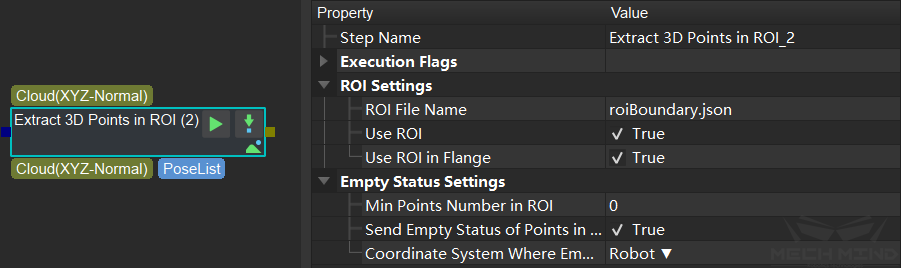
Figure 7 Extracting point cloud in ROI
Down-Sample Point Cloud
This step is used to sample the point cloud to reduce the size of the original point cloud. For most projects that do not have high requirements for point cloud density (such as edge matching, obtaining the highest layer mask, etc.), adding this step can greatly improve the beat. Sampling interval The sampling magnification can be controlled and set according to the beat requirement.
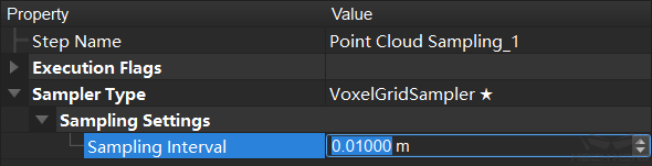
Figure 8 Down-Sample Point Cloud
Calculate the Normal Vector of the Point Cloud and Filter
After the depth map is converted into a point cloud, the normal vector of the point cloud needs to be calculated and filtered. For a host computer with a suitable supporting graphics card (GPU), setting the normal calculation method of GPU acceleration can significantly improve the beat.
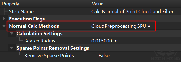
Figure 9 Calculate the normal vector of the point cloud and filter
Point Filter
This step filters the points in the point cloud through the set rules to eliminate noise. In order to improve the beat, you can modify the number of nearest neighbors used for the average distance estimation, and conduct an experimental test. On the basis of ensuring the accuracy, the parameter can be appropriately reduced.
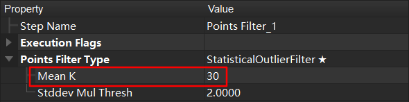
Figure 10 point filtering
Point Cloud Clustering
This step includes the GPU acceleration option. When there are a large number of point clouds, checking this option will increase the beat, otherwise there will be no obvious effect. It is worth noting that when the video memory is insufficient (for example, viz/deep learning takes up too much), it may not decrease but increase, and the parameters should be set according to the actual situation.
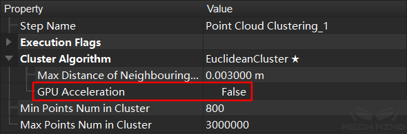
Figure 11 Point cloud clustering
3D Matching
3D Matching mainly includes steps 3D Coarse Matching and 3D Fine Matching. Wherein 3D Coarse Matching is mainly used to calculate the approximate position of the template point cloud in the space point cloud, and 3D Fine Matching is mainly used to match the template with the space point cloud. The calculation principles of these two steps are similar, they need to calculate the relative position of each point in the space. Therefore, the more points, the more time will be spent, and the more iterations of the fine matching will also take more time. Therefore, when adjusting these two steps, it is mainly to reduce the number of processing point clouds (data and templates) and reduce the number of iterations (fine matching).
Tip
For rough matching, if you select
SurfaceMatching, adjustSampling Settingsto adjust the point cloud density to reduce calculation time. In the case where the density of the down-sampled point cloud cannot be lower, but still needs to increase the beat, consider increasing thereference/reference point sampling step.Remove a lot of useless point clouds through some early point cloud preprocessing work, such as clustering, ROI, point cloud filtering and other operations.
When multiple workpieces are matched, the number of matched workpieces can also be appropriately reduced. For example, only 3 workpieces are matched each time to increase the matching speed.
According to the characteristics of the actual workpiece, the template file is simplified. For example, the edge template is used to match the large workpiece, or the template is down-sampled to reduce the number of point clouds to a smaller range.
Point direction calculation method: For the template that cannot be directed, use
StandardMode; for the edge plane object template, useEdgeTangent, while ensuring that the recognized object has been well segmented.
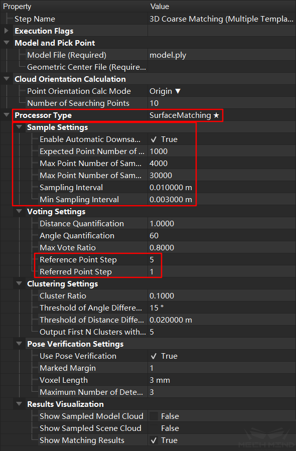
Figure 12 3D coarse matching
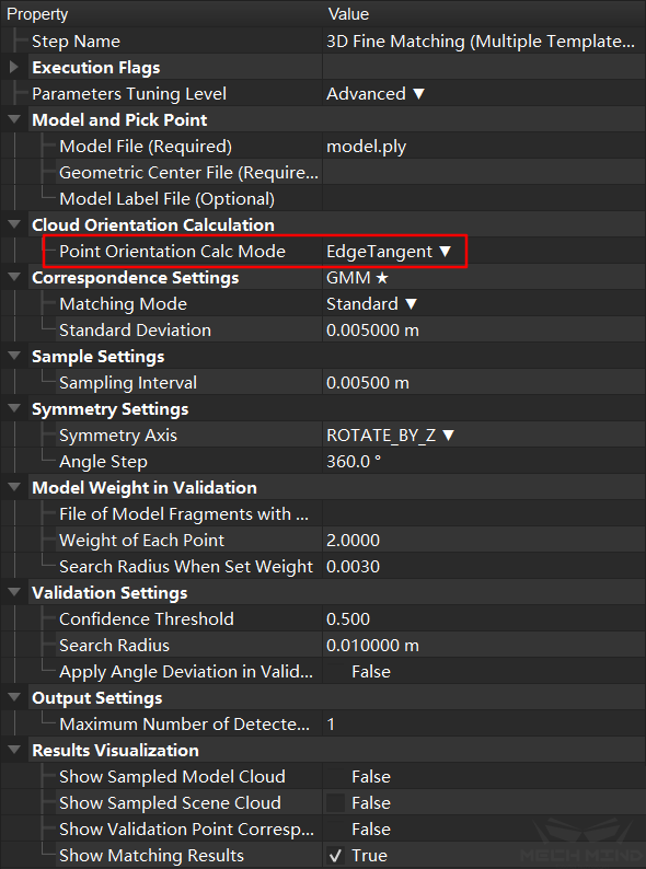
Figure 13 3D fine matching
Others
In the project, in addition to Capture Images from Camera and 3D Matching, there are many other Steps. The time consumption for most of the steps can be ignored. If necessary you may make appropriate adjustments according to Mech-Vision Guide to Steps .
IPC (Industrial Personal Computer) Performance Improvement
Computer vision and image processing is very computer-intensive. A good-perf rmance IPC (Industrial Personal Computer) can greatly improve the overall speed. Mech-Mind provides IPCs with a minimum configuration of I7 8700 + 1050TI. Configuring a higher CPU and GPU will bring better results.
Tip
3D Matching mainly consumes CPU resources, while deep learning consumes more GPU resources.
Mech-Viz, Robot
Route Optimization
Robot path optimization mainly refers to the reduction of unnecessary fixed points and unnecessary actions during the movement of the robot. Therefore, the central idea of path optimization is to reduce fixed points and reduce detours.
Tip
The main operations include the following:
Reduce detours, try to reduce redundant intermediate points in a section of motion without collision, and ensure the smooth operation of the robot.
Reduce fixed points, in order to ensure robot movement in the early stage.
Reduce rotation. During the robot’s grasping process, the fixture may rotate more than 180°. Through the control of vision engineering and the adjustment of symmetry, this kind of situation can be reduced. Using relative_move at the same time can directly avoid excessive rotation.
General Parameters of Move Skills, adding no waiting to the steps of most sports can improve the fluency of the robot and reduce pauses.
To improve the smoothness of the robot’s motion trajectory, the turning radius function can also be used appropriately and reasonably to avoid fixed points on the robot’s walking line. At the same time, use more joint motions, reduce the use of longer linear motions, and reduce the possibility of the robot moving to singular points. When necessary, use multi-segment joint motions instead of long-distance linear motions to prevent uncontrollable motion states at long distances. For the setting of turning radius and movement type, please refer to Basic Move General Parameters
Avoid singularities. According to the design of Mech-Viz software, when the robot is about to cross the singularity, the robot will slow down appropriately to prevent the robot from reporting errors. Similarly, in the process of workpiece grasping, the robot should try to avoid moving to the vicinity of the singular point to prevent error stop or slow running caused by the singular point. For parameter settings, see Operation Settings
Speed of Robot
When the robot’s workflow is determined, and it can work slowly and stably, the speed of the robot can be gradually increased to the highest speed. The increase on the speed can greatly improve the takt time.
Tip
The speed of each move of robot can be adjusted directly in Mech-Viz.
Speed of movement module in Mech-Viz
When using Mech-Viz for movement tasks, the default Basic Move General Parameters is that the acceleration is 50% and the speed is 100%. When the route optimization is completed, the speed and acceleration for each module can be adjusted respectively to achieve control of the speed and acceleration on the robot in different situations.
Tip
When the robot is not grasping the workpiece, the speed and acceleration can be gradually adjusted to the maximum allowable value.
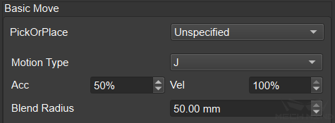
Figure 14 Move speed control in Mech-Viz
Speed of Movement Tasks
When the Mech-Viz software uses movement tasks, Basic Move General Parameters defaults to acceleration 50% and speed 100%. After the path optimization is completed, the speed and acceleration of each module can be adjusted separately, and the speed and acceleration of the robot can be controlled under different conditions.

Figure 15 Movement speed control in Mech-Viz
Shooting Process and Timing
In Mech-Viz, visual_look can be used to trigger shooting and the visual data will be processed and outputted via Mech-Vision, the processed results will be used in visual_move to control the robot to move to the specified position. The process for processing the data can run in the background, that is, during the move of the robot, it will process the obtained new data and be ready for the next grasping.
Tip
In Mech-Viz, visual_look can be used to trigger shooting and the visual data will be processed and outputted via Mech-Vision, the processed results will be used in visual_move to control the robot to move to the specified position. The process for processing the data can run in the background, that is, during the move of the robot, it will process the obtained new data and be ready for the next grasping.
In Eye in Hand mode, after the robot grasping the workpiece, the camera can directly take a picture, and perform data processing in the background. When the first workpiece is placed by the robot, it can directly grasp the second workpiece.
Hint
In some projects about depalletizing cartons, when ensuring that other boxes will not change after each grasping, the solution of one shot and multiple grasping can be used. Mech-Vision can recognize multiple objects at one time and provide all poses during each recognition process. Therefore, just with one-time recognition, the robot grasps all the recognized cartons and re-shoot after grasping, which can save a lot of camera time.
Similarly, if the end effector is large enough, you can control the robot to grasp multiple box in different position at one time to improve the takt time of grasping.