Error control
In the project implementation, one of the most commonly encountered problems is the grasping error. The grasping error is that during the process of grasping the workpiece by the controlled robot, it is found that the robot did not reach the ideal position, instead certain error existing. The causes of errors are various, and they will be analyzed from the three aspects of the extrinsic parameter, vision, and robot. The detailed structure is shown in the figure below.
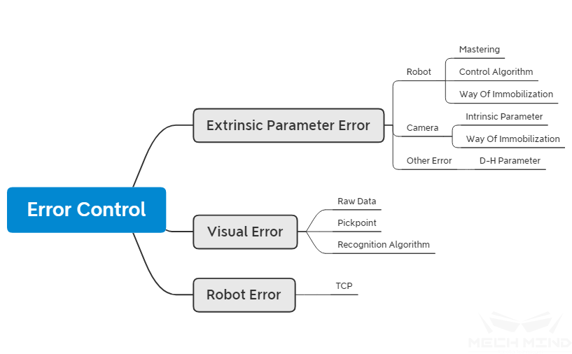
Figure 1 Causes for grasping error
Extrinsic parameter error
Robot
Null point
- Null point:
The robot controls the movement of each axis for the robot motor via a closed-loop servo system, and controls each motor by the instructions of the controller. The pulse encoder installed on the motor can feedback the signal of the motor to the robot. During the robot’s movement, the controller continuously receives and analyzes the signal returned by the encoder, so as to achieve the correct control of the robot during the entire movement. The controller accurately analyzes the information returned by the encoder based on the null point position of each axis, so that the position of the robot can remain unchanged during the operation. During the normal operation of the robot, the null point position and the joint position of the robot will be saved, and the internal battery will be used to maintain power when the controller is normally powered off. This data will be saved every time the robot is shut down normally. Each time the robot is powered on, it will directly read the data in the backup for identification to ensure the same state as when the power was off. The null point of the robot may be shifted or lost under conditions such as impact, battery power loss, or unused for a long time.
If the robot is working under the circumstance that the null point is missing, it will cause:
The robot’s joint axes work beyond the soft limits (this is very dangerous);
The robot cannot reach the specified position , different null point position results in different robot end positions under the same joint angle;
The robot cannot move the specified length in the specified direction (such as unable to walk 1 meter correctly).
When using Mech-Vision to calibrate extrinsic parameters, it calculates the points to reach for the multiple robots based on the calibration parameters. When the null point of the robot is lost, it is often impossible to reach the point accurately, and errors occur in the result for the calculation of the extrinsic parameter in the end.
Tip
There are many ways to detect whether the robot null point is missing. Here are two of the most commonly used detection methods:
Adjust the angle of all axes of the robot to 0° by the teach pendant, and then observe whether the nameplates on the axes of the robot are aligned. If they are not aligned, it is indicated that the robot null point is lost;
Control the robot to move a certain distance along the specified direction and observe whether the robot’s walking distance is consistent with the theoretical distance.
Determine the null point of the robot by the above method, and then the null point calibration of the robot can be performed according to the null calibration method on the different robots.
Control Algorithm
Some newly developed robots have problems with the control algorithm at a low probability, that is, the robot cannot move to a specified position, and there is a deviation. In the case that the robot cannot accurately move to an accurate position, the robot cannot perform the tasks calibrated by the extrinsic parameters in the future.
Fixing
The fixing method of the robot directly determines whether the robot can maintain stability during the long-term operation. Weaker fixing methods, such as the use of expansion bolts or large bases that are not fixed, it cannot guarantee that the robot will remain stable or keep the running at high speed during the long-term operation. If the robot moves, the position relationship between the robot and the camera is destroyed in practice, and the robot will not grasp accurately. This situation is not common and once it happens it is difficult to be detected. Therefore, it is necessary to confirm the fixing method of the robot when fixing the robot.
Tip
If the long-term operation is required, it is best to use chemical bolts for fixing, and then perform the robot operation after the chemical bolts are firmly fixed, otherwise it will cause the bolts to loose;
If the short-term operation is required, such as exhibitions, the robot can be fixed on a relatively stable surface, but the speed of the robot cannot be adjusted to a particularly high level, otherwise it will cause the robot to loose.
Camera
Intrinsic parameter
The extrinsic parameter problems caused by the camera’s intrinsic parameters mainly occur at the edge of the camera’s field of view or exceed the working distance of the camera. By factory defaults, the reasonable working distance of the camera according to the hardware used was determined. When the camera is working beyond the working distance or edge, because the camera is not accurately calibrated at this position, it will cause deviations in the generated point cloud, and finally it will also cause deviations in the calculated extrinsic parameter.
Tip
It is recommended that when using the camera, it is necessary to determine the working distance of the camera, and check whether the intrinsic parameters of the camera are correct, and finally perform calibration on the working distance of the camera.
Fixing
The reason for the change of the extrinsic parameters on the camera caused by the fixed method is the same as the fixed method of the robot. The stability of the fixed method directly determines whether the station can be used for a long time and keep the extrinsic parameters stable. For details on how to install the camera, please see Mounting the Camera.
Tip
The severe collisions on the camera support or large vibrations may also cause the camera support to become loose. Take special care when fixing and prevent the camera support from being bumped and leaned against.
Other errors
In the process of initial adaptation of the robot, in order to obtain the kinematic relationship of the robot, it is necessary to find the operation parameters of the corresponding robot (hereinafter referred to as D-H parameters) in the major robot websites or instructions. The relationship between the joint axes of the robot can be established by obtaining the operation parameters of the robot. In the actual process, the D-H parameters in the software may be inconsistent with the D-H parameters of the actual robot. There are two possible reasons:
- This may be due to the difference
error in the number of robot sub-models or the obtained D-H parameters have a certain error with the actual robot;
- There is a difference between the
manual and the actual robot.
If the D-H parameters are inconsistent, the end position of the robot in the software may be different from that in the teach pendant, which will cause the extrinsic parameter deviation during the calculation.
Tip
To check whether D-H parameters are consistent. After connecting with the robot, observe whether the posture of the 6-axis end of the robot is consistent with the robot end in Mech-Viz under the condition that joint angle is consistent. If they are not consistent, it may be caused by the deviant D-H parameters.
Vision error
Raw data
- Raw data:
Raw refers to the raw data input to Mech-Vision for processing. The data content mainly includes RGB images and depth images.
When the light (such as day to night) is changed on the work site, the configuration parameters on the camera are not updated in time, which may cause:
The collected point cloud has too much noise or the details are not obvious, making subsequent matching algorithm unable to continue or identify errors;
The quality of the collected RGB images changes, and the brightness of the images collected in a dark environment is not enough, resulting in no results in deep learning or poor recognition results.
Tip
If the above situation occurs, the camera parameters in Mech-Eye Viewer is required to be updated, and adjust the 2D and 3D exposures respectively, so that the RGB image and the depth image have better results. Or in project deployment, apply ideal Illumination control
Grasping point
Grasping point error is one of the common errors. There are two methods to set the grasping point in Mech-Vision, one is dragging grasping point, and the other is teaching grasping point. The teaching grasping point has a small error under the condition that the robot is accurate, so this situation is not considered here, and the situation of dragging grasping point will be analyzed.
Dragging grasping point is required to be performed in Mech-Vision. Adjust the position of the grasping points based on the template. Dragging grasping point is an inaccurate method, and the position to be reached by the robot cannot be provided accurately, so an ideal position cannot be reached in the actual grasping process. If a more accurate grasping point is required, it is necessary to use the teaching method to obtain the grasping points.
Tip
If there are errors in the grasping points, you can directly find them from the coordinates on the point cloud in the Mech-Viz software whether the grasping points of each workpiece are in the ideal position.
Algorithm
Deviations due to the output by Mech-Vision are collectively referred to as algorithm errors here. The deployment of vision algorithms is often set based on the original images collected on site. If the changes in lighting and working environment occur, the original parameters may not be applicable. It can be found in Mech-Vision and adjusted according to the instructions of the software user manual. Meanwhile, the recognition of some special workpiece may lead to sporadic errors, that is, no problems occur during the long-term operation, and occasional recognition errors occur due to the environmental changes, especially for the axisymmetric objects, the local optimal solution will occur, which leads to recognition error.
Attention
Errors may occur due to template errors on some sites, that is, the template obtained via the STL file is inaccurate with the actual object to be captured, which will cause that the best results cannot be obtained when performing the template matching. The possible reasons for this are
The STL file is the file for the finished product, but the file to be grasped is the file for the rough material. In the production process, a machining allowance is left to ensure subsequent processes, which results in the workpiece that needs to be identified is larger than the template file.
At this time, you can adjust the scaling of the template appropriately.
Robot error
TCP
The TCP error of the robot manifests itself as an inconsistency between the actual tool center and the theoretical tool center of the robot. Most of the reasons are that the robot TCP calibration is not accurate enough. The situations such as the movement of the cusp, the robot’s posture change is not large enough, and it does not coincide with the cusp, etc., all may cause the inaccuracy of the robot TCP. During the use of the software, it is required to create a tool in Mech-Viz and enter the correct TCP value.
Tip
To determinate TCP, a better method is to use a robot to calibrate TCP, and enter the calibrated value into Mech-Viz, and leave a backup on the robot side.
Tip
For a project which does not require the high accuracy, directly adjust the TCP value in the software to improve the accuracy of the grasping.