3D Coarse Matching
Function
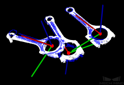
Roughly match the model point cloud with the original point cloud, and output approximate candidate poses of the target candidates.
Sample Scenario
This Step is usually used to detect the target object in the scene point cloud and obtain approximate candidate pose. This Step is usually connected with the Step 3D Fine Matching.
Input and Output
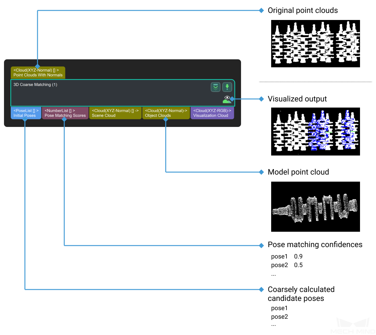
Parameters
Model and Pick Point
The path of model file and pick point file.
- ModelFile
- Geometric Center File
Cloud Orientation Calculation
- Point Orientation Calc Mode
Origin: Use the original normal of the input point cloud directly.
StandardMode: Use the CPU to recalculate the normal direction of the input point cloud, which is recommended when the model does not have the normal direction. The k points nearest to the target point were searched, and PCA (principal component analysis) is used to obtain the minimum feature vector as the normal direction of the point.
EdgeTangent: The tangent direction of the input edge point cloud is calculated as the normal direction. Objects whose outer contours are mirror images of each other can be distinguished. It is recommended to match edge point clouds of flat objects.
EdgeNormal: Calculate the normal direction of the input edge point cloud, and use the tangential direction of the point as the normal direction, which is recommended for matching the edge point cloud of a flat object.
Note
When using the EdgeTangent or EdgeNormal method, ensure that each edge point cloud does not contain multiple objects; in other words, each object point cloud is separated.
- Number of Searching Points
Processor Type
Default Value: SurfaceMatchingEasyModeList of Values: SurfaceMatchingEasyMode, SurfaceMatchingInstruction: There are two types of this algorithm. The Resultant Visualisation is set to parameters that can be adjusted for both algorithms. The algorithm type parameters are adjusted using Figure 1as an example of an input point cloud, starting with the adjustable parameters in the SurfaceMatchingEasyMode algorithm.
SurfaceMatchingEasyMode algorithm: The adjustable parameters module is Speed Controller and Output Settings .
SurfaceMatching algorithm: The adjustable parameters module is Sample Settings Voting Sttings and Pose Verification Settings
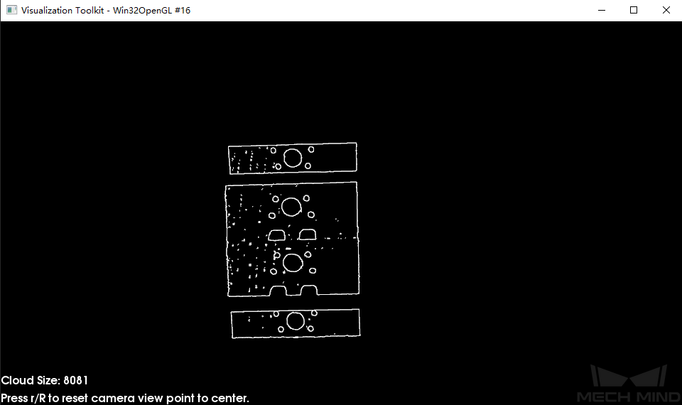
Figure 1 Example of Input Point Cloud
Speed Control
- Main Speed Controller
2, and the right figure shows the result when this value is5. It is obvious that the matching accuracy decreases after adjustment.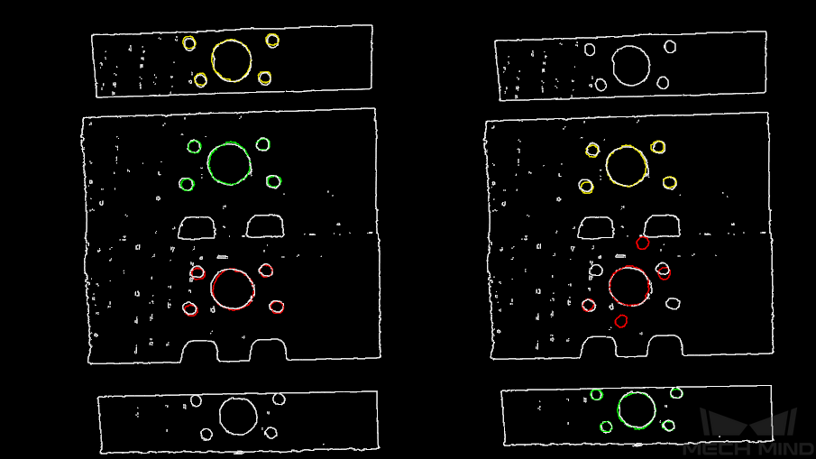
Figure 2 Comparison of Adjustment Results of Main Speed Controller
- Secondary Speed Controller
10, and the figure on the right shows the result when this values is15. It can be seen that the matching accuracy decreases after adjustment, but the influence is less than that of the main speed control parameters.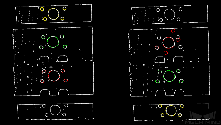
Figure 3 Comparison of Adjustment Results of Secondary Speed Controller
Output Settings
- Maximum Number of Detected Poses in Each Point Cloud
3, and the right picture shows the result when the parameter is10.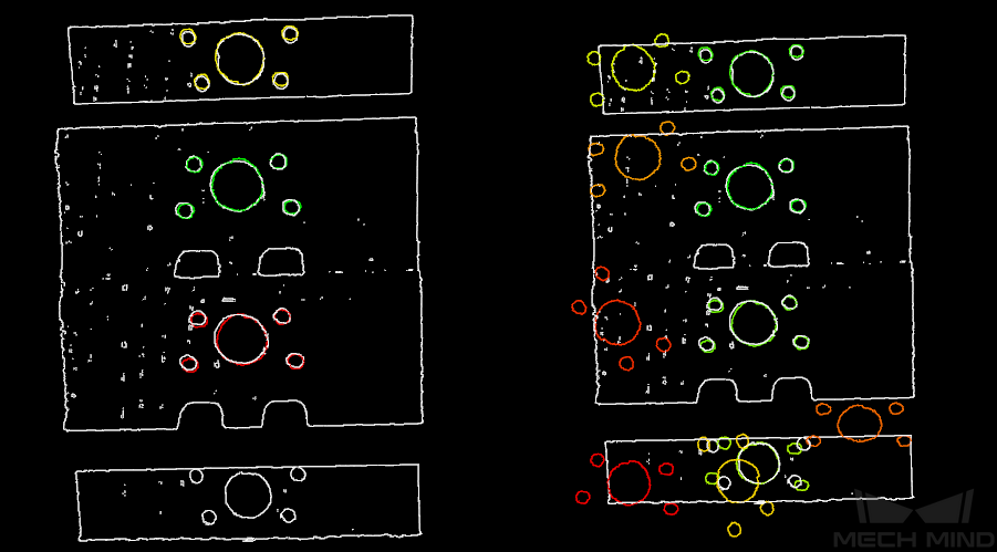
Figure 4 Comparison of Parameter Adjustment Results of Maximum Number of Detected Poses in Each Point Cloud
The parameters of SurfaceMatching are described below.
Sample Settings
- Enable Automatic Downsampling
True, the sampling interval parameter of model point cloud will be automatically adjusted according to the expected points of the model after sampling.- expected Point Number of Sampled Model
- Max Point Number of Sampled Model
- Max Point Number of Sampled Scene
- Sampling Interval
0.01, and the right picture shows the result when the parameter is0.02.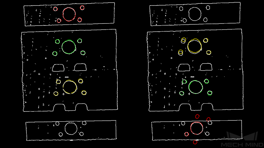
Figure 5 Comparison of Sample Interval Parameter Adjustment Results of Model Point Cloud
- Min Sampling Interval
Voting Settings
- Distance Quantification
- Angle Quantification
- Max Vote Ratio
- Reference Point Step
- Referred Point Step
Clustering Settings
- Cluster Ratio
0.1means that the top 10% pose is taken as the pose for clustering. The larger the value, the more likely it is to find an accurate match, but the running time increases accordingly.- Threshold of Angle Difference
- Threshold of Distance Difference
- Output First N Clusters with High Scores
Pose Verification Settings
- Use Pose Verification
Trueis checked, all cluster parameters are invalid. Pose validation and clustering are two different methods for verification and screening of final matching results, which cannot be used simultaneously.- Marked Margin
- Voxel Length
- Maximum Number
3, and the right side is the result when the parameter value is5.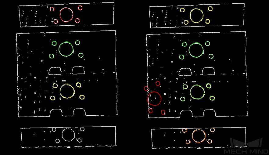
Figure 6 Comparison of Maximum Number Parameter Adjustment Results
Results Visualization
- Show Sampled Model Cioud
- Show Sampled Scene Cioud
- Show Matching Results