Camera Mounting
Robot-Camera Architecture Setup
A camera can be mounted based on two types of architecture:
Eye-in-hand (EIH): The camera is rigidly mounted on the robot end flange plate and moves with the robot.
Eye-to-hand (EIH): The camera observes the robot from a fixed external point, typically above the object from a certain height.
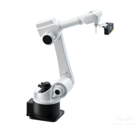
Figure 3. Eye in Hand
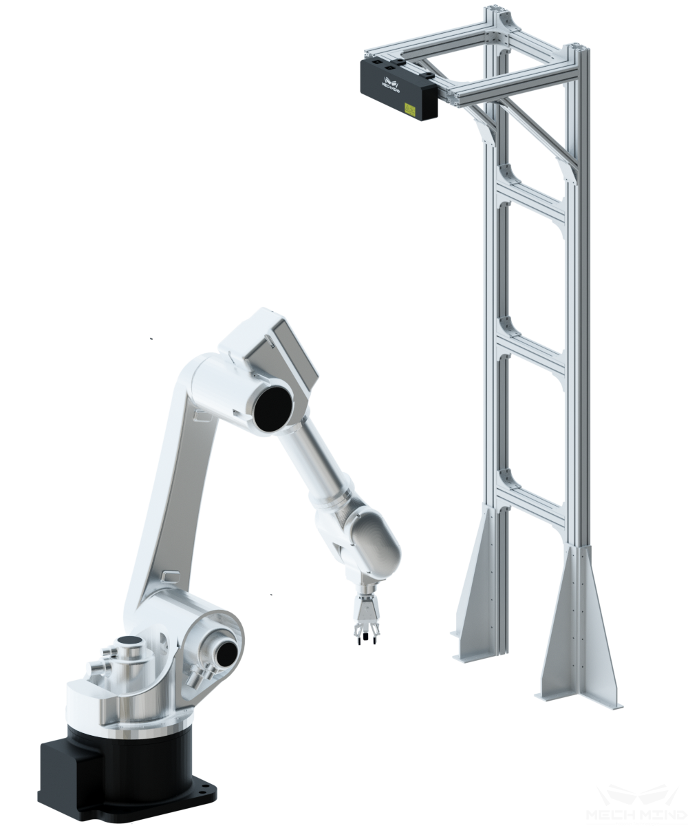
Figure 4. Eye to Hand
The camera must be connected with cables and signal wires from Mech-Mind to ensure the quality of signal transmission and reduce noise. For EIH, please ensure that the supplied camera cables attached to the robot are put inside the dress pack to avoid any damage.
Hint
Please add extension cords when necessary.
Camera Stands
The camera can be fixed on the stand or can slide horizontally on the stand, as shown below.
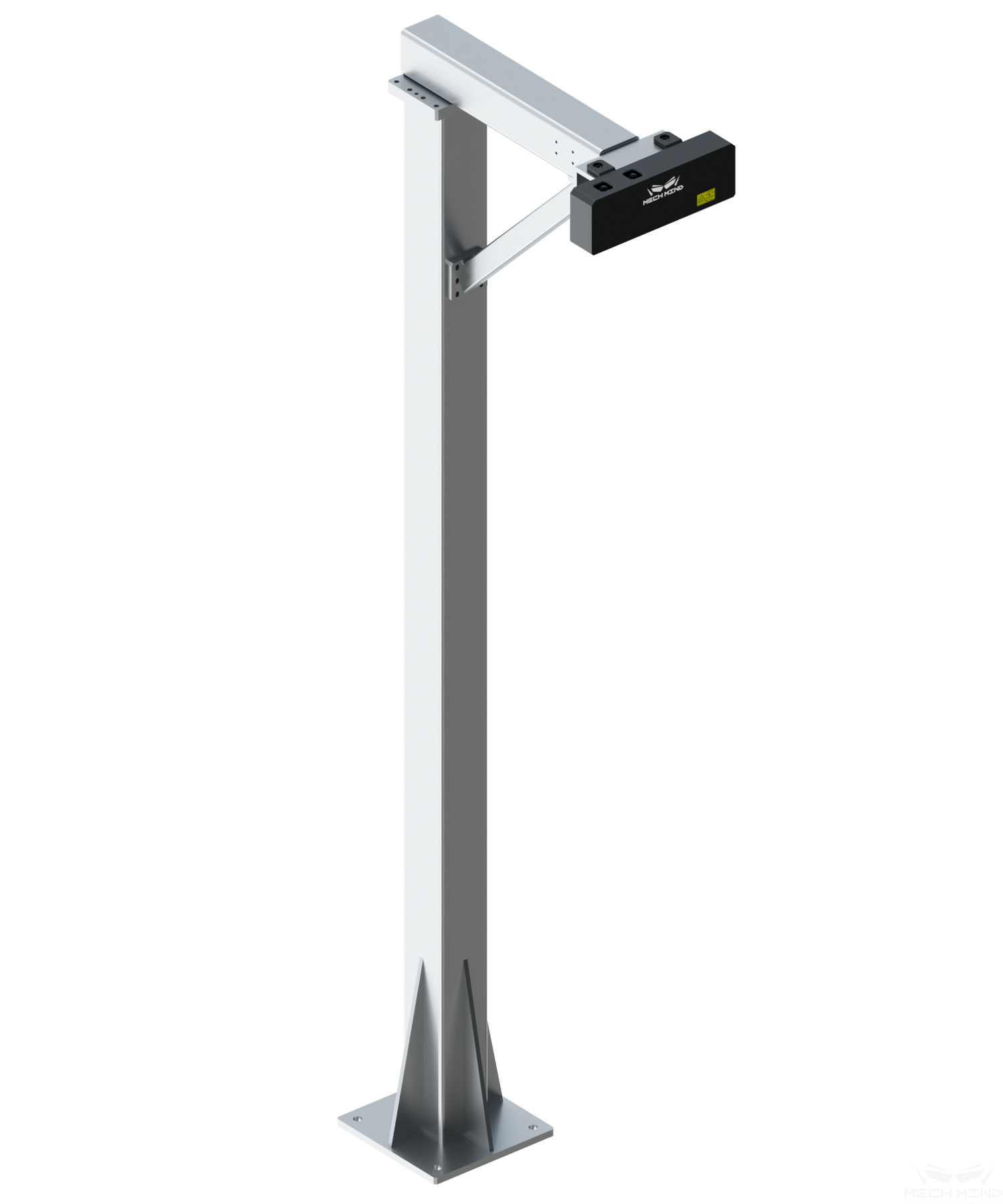
Figure 5. Camera stand with fixed mounting point

Figure 6. Camera stand with slide rail
Based on the experience of earlier projects, if the camera supporting stand have issues with stability, reliability, and fixation firmness, intrinsic and extrinsic parameter errors will occur, and the camera lens will go loose, which affects the debugging progress and reliability of subsequent operations. Therefore, the following requirements are specifically proposed for the design and mounting of the camera supporting stand:
For demonstrational projects, a temporary camera stand of the European Standard 8080 profile will suffice; for practical projects, a steel structure camera stand is recommended.
All the main parts of the temporary camera supporting stand should be of European Standard 8080 profile. Only the triangular supports can be of the European Standard 4080 profile. At least two posts are needed to erect the stand.
For steel structure camera stand, the main parts should be of steel square bars, with a size of at least \(100 × 100 × 6 mm\) , a recommended size of \(100 × 100 × 8 mm\) and above; the thickness of the bottom plate should be more than 10mm with a size of \(300 × 350 mm\) and above.
The camera supporting stand should be anchored to the floor with chemical bolts. Expansion bolts should not be used.
For Eye in Hand, please make sure the camera is mounted on a sufficient height with no obstruction in the field of view.
All parts of the braskt should be far away from any lines, cables, cords, wires. Otherwise, the reachable space of the end effector and calibration accuracy and efficiency will be severely affected.
Recommended camera stand designs:
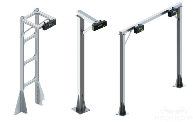
Figure 7. Several camera stand designs:
Left: temporary camera stand
Middle: steel structure stand
Right: Gantry stand
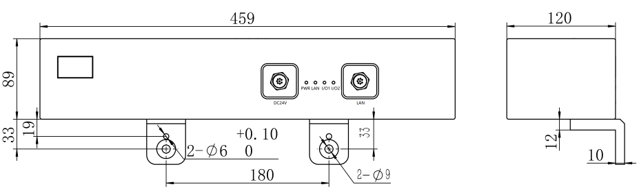
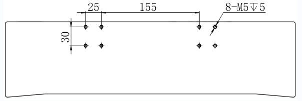
Fixation Dimensions of All Camera Models
Model |
Fixation Dimensions for Type A (the upper) and Type B (the lower) |
Nano |
|
|
|
Log S |
|
|
|
Log M |
|
|


Model |
Fixation Dimensions for Type A (the upper) and Type B (the lower) |
Pro S Enhanced |
|
|
|
Pro M Enhanced |
|
|
|
Deep |
|
|
|
Laser L |
|
|

Right-Angle Brackets
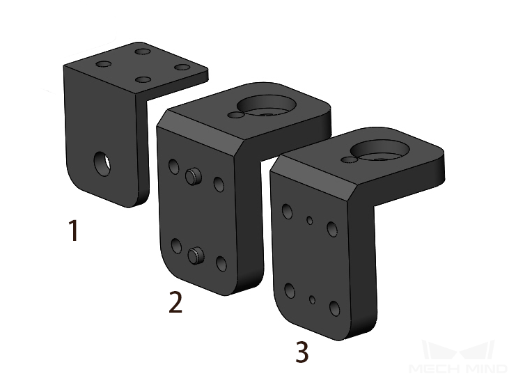
No. |
Name |
Applicable Camera Models |
1 |
Nano V3 |
|
2 |
Laser L V3S Series |
|
3 |
Deep, Log S, Log M Series |
Please click on the names for detailed dimensions.