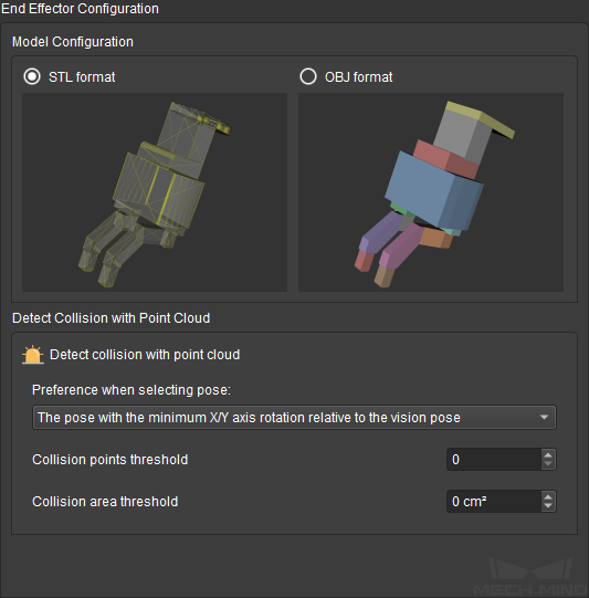
2. End Effector Configuration
In this pane, you can select the format of robot tool model used and configure the detection of collisions between the robot tool and point cloud.
Note
Collisions between the following object pairs involving the robot tool are checked by default and cannot be configured:
Robot links and robot tool
Scene objects and robot tool
Configurations made in this pane only takes effect if you have added a robot tool model. For instructions, please refer to Add an Model.
2.1. Model Configuration
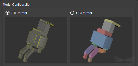
Select the format of robot tool model you added, STL or OBJ.
The different formats affect the detection of collisions between the tool and point cloud. With OBJ format, collisions with the interior of the robot tool can be detected.
STL
OBJ
Model type
Mesh (linked triangles)
Assembly of convex polyhedra (solid)
Industrial 3D modeling
Widely used
Rarely used
Collision detection
Only collisions with the surface can be detected
Precise and efficient
Parameter adjustment
difficult for complicated applications
Relatively easy and highly adaptable
For more detailed information on the two file formats, please refer to Basic Principle of Collision Detection.
Attention
Starting from version 1.6.0, OBJ models that contain concave polyhedra cannot be used for collision detection anymore. OBJ models used in collision detection must be fully made of convex polyhedra.
Parameters in the Detect Collision with Point Cloud section is automatically adapted to your selection in the Model Configuration section. The following sections introduces the parameters by model format.
2.2. Detect Collision with Point Cloud - STL
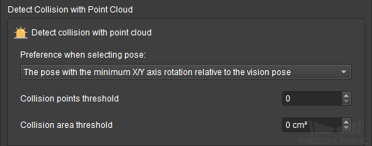
Preference when selecting pose: candidate workobject target poses are generated by rotating from the received vision pose according to Configuration of Objects to Pick in the Tools and Workobjects tab. Your selection here affects how the target pose is determined.
The pose with the minimum X/Y axis rotation relative to the vision pose: select the first candidate pose (i.e., the least rotated about the X- or Y-axis) whose collision is below the set threshold as the target pose. Once selected, computation of candidate poses is stopped.
The pose with the minimum collision within the X/Y axis rotation range: compute all candidate poses and select the pose with the least collision as the target pose.
Collision points threshold: set how many points in the point cloud are allowed to collide with the robot tool at a target pose.
The default value is 0 (no contact between the robot tool and point cloud is allowed).
Collision area threshold: set how large an area of the tool model is allowed to collide with the point cloud at a target pose.
The default value is 0 (no contact between the robot tool and point cloud is allowed).
2.3. Detect Collision with Point Cloud - OBJ
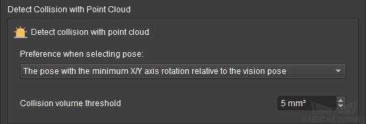
Preference when selecting pose: candidate workobject target poses are generated by rotating from the received vision pose according to Configuration of Objects to Pick in the Tools and Workobjects tab. Your selection here affects how the target pose is determined.
The pose with the minimum X/Y axis rotation relative to the vision pose: select the first candidate pose (i.e., the least rotated about the X- or Y-axis) whose collision is below the set threshold as the target pose. Once selected, computation of candidate poses is stopped.
The pose with the minimum collision within the X/Y axis rotation range: compute all candidate poses and select the pose with the least collision as the target pose.
Collision volume threshold: set how large a volume of the tool model is allowed to collide with the point cloud at a target pose.
The default value is 5 (contact of 5 mm3 or less between the robot tool and point cloud is allowed).
2.4. Tips for Parameter Adjustment
The key factor to consider is: whether it is okay for the robot tool to touch or even move other workobjects during picking.
Consider picking up jelly beans with chopsticks. Even if the chopsticks touch or move other jelly beans when picking up a jelly bean, these other jelly beans will not be adversely affected (e.g., broken).
In cases like this, such as picking up randomly piled small metal workpieces from a bin, you can set higher collision thresholds and allow some collision to occur, so that a higher rate of successful picking can be guaranteed. However, you should note that the picked workobject might also move when the tool touches/moves other workobjects.
In cases where collisions might break the workobjects or have other adverse effects on the application, you should decrease the collision thresholds to ensure the planned path is collision-free.