End Effector Configuration
In order to facilitate picking, you can configure the end effector in the Tools and Workobjects panel.
This section covers the following topics:
End Effector Configuration Panel
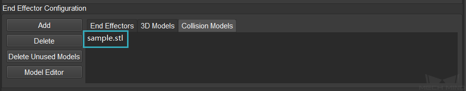
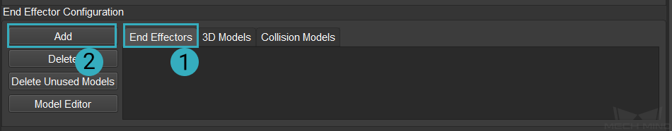
The end effector configuration panel is shown below.
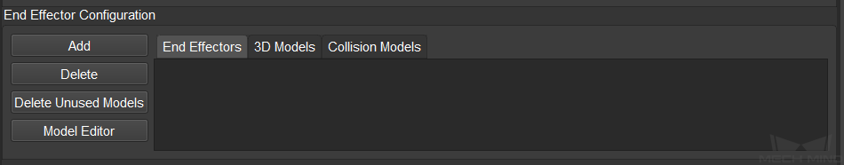
The functions of the tabs and buttons are described as follows.
End Effectors: displays the added end effector models.
3D Models: displays the added 3D models.
Collision Models: displays the added collision models.
Add: adds an end effector model, 3D model, or collision model.
Delete: deletes a selected end effector model, 3D model, or collision model.
Delete Unused Models: deletes unused 3D models or collision models.
Model Editor used to simplify models. Please refer to Model Editor for detailed information.
Hint
When multiple end effector models are added, the first one in the list will be used by default.
You can also right click on the added model and select Delete to delete the model.
Add an Model
Adding a 3D model and collision model may facilitate collision detection and path planning in Mech-Viz.
3D models can only be used for visualization, while collision models can be used for collision detection as well. Therefore, adding a collision model is more recommended.
If the collision model is in OBJ format, please read Notes for OBJ Collision Models first to avoid collisions.
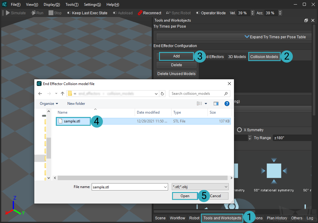
Click on the Tools and Workobjects tab, and then go to the End Effector Configuration panel. Select , select the model file you need in the file selection window, and then click on Open.
Model Type
Instruction
OBJ models that are entirely composed of convex polyhedra
Load normally
OBJ models not entirely composed of convex polyhedra
Follow the instruction in the pop-up window to convert the model
The pop-up window that suggests to convert the model is shown below.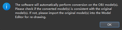 Click OK to convert and load the model. The shape of the converted model may change. In this case, please use Blender or Model Editor in Mech-Viz to edit the models before importing to make sure that the model can meet the requirement.
Double click on the added model in the Collision Models list.
Configure the parameters in the pop-up Edit Model Transform window.
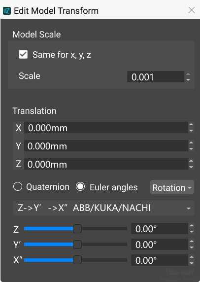
The functions of the buttons and options in the window are described as follows.
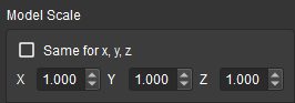
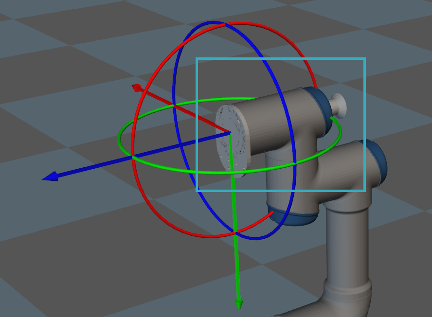
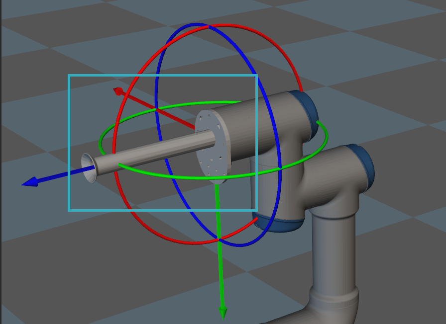
Model Scale: scale the model by setting the model scale. The figures below show an example of setting different model scales.
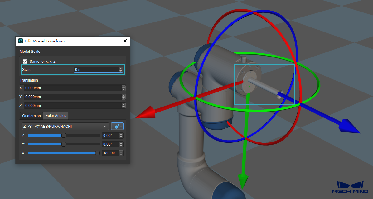
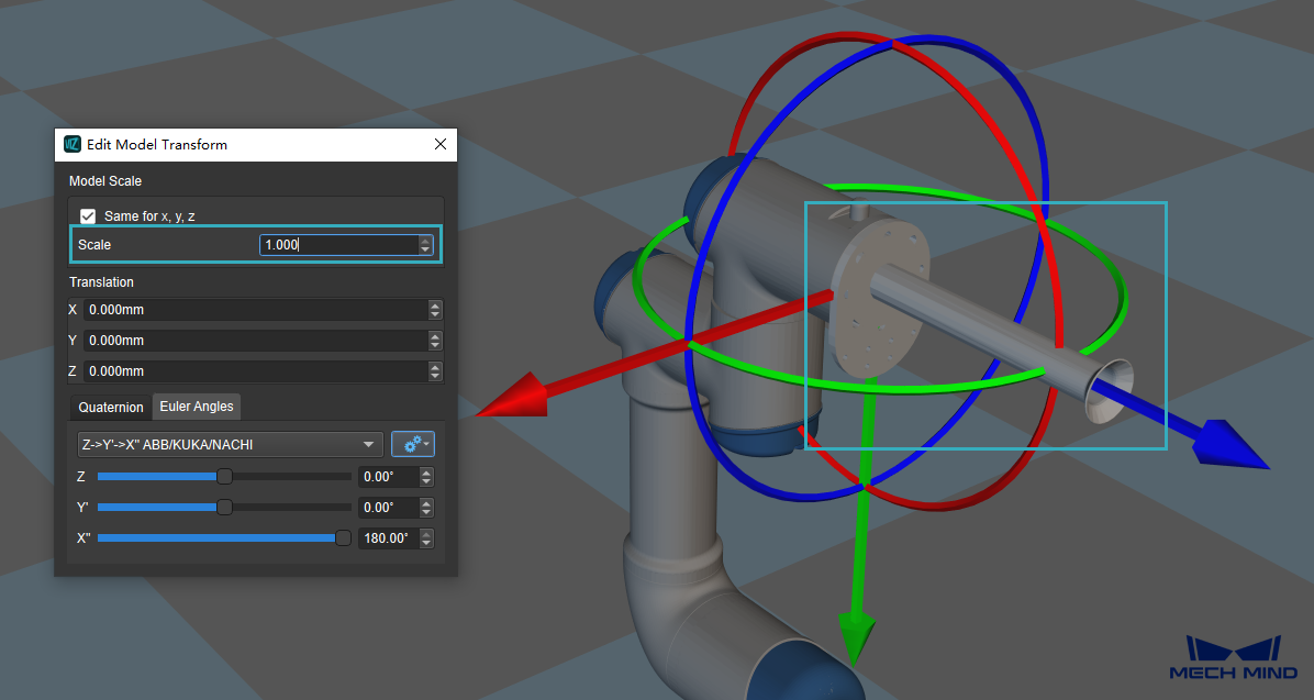
If you need to scale the model in the X, Y, or Z-direction independently, please uncheck Same for x, y, z and enter the scale ratio in the X, Y, or Z-direction respectively.
Translation: adjust the position of the collision model to the robot flange by adjusting the value of X, Y, and Z.
Click on the added collision model in the Collision Models list and check whether the position of the model is correct. The figure below shows an example of incorrect position of the collision model. The vacuum gripper is embedded into the robot model.
You can adjust the position of the collision model by entering a value or scrolling the bar to adjust the X, Y, and Z coordinate.
The correct position of the collision model is shown below.
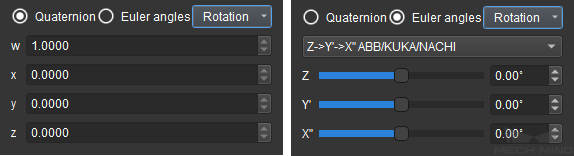
Quaternion and Euler Angles: quaternion and Euler angles are introduced to describe the rotation of the model. You can enter a value or scroll the bar to configure the rotation.
Recommended Method for Using Models
For projects without specific requirements for displaying, it is recommended to add a collision model only instead of adding a 3D model. The reasons for doing so are as follows.
The file size of the project can be reduced. A 3D model for visualization usually contains more details and therefore the file size is larger.
The setting process can be simplified. If both the 3D model and collision model are added, you will need to adjust the position of two types of models separately when adjusting the position of the end effector. If only the collision model is added, you can just adjust the position of the collision model.
The dimensions of the model should be slightly larger than the actual end effector. The reasons are as follows.
There is a deviation between the planned path and the actual path that the robot takes.
Due to the deviation of the end effector itself and different installation methods, there may be a difference between the model and the actual end effector.
The length of the model in the Z-direction should be slightly shorter than the actual length.
When a vacuum gripper or cushion spring is used, a certain degree of compression should be allowed in the Z-direction. In order to ensure the accuracy of the collision detection, it is recommended that the length of the model in the Z-direction should be slightly shorter than the actual length.
Note
In the tool reference frame, the Z-direction is defined as the path that the end effector takes to approach the work object. The length of the Z-direction refers to the distance between the TCP (tool center point) and the surface of the robot flange.
It is recommended to simplify the model.
A model with more detailed surface features will increase the computational effort in collision detection. In order to reduce the computational effort, it is recommended to simplify the model. Common practices to simplify models include removing faces inside the model, replacing curved surfaces with flat surfaces, etc.
Please refer to STL Models Simplification and OBJ Models Simplification for more detailed instructions.
Configure the End Effector Model
After adding a collision model, you will need to add and configure the end effector model and define a TCP.
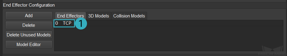
Click on End Effectors in the End Effector Configuration panel, then click on Add. Configure the parameters in the pop-up Edit End Effector window, and click on OK to save settings.
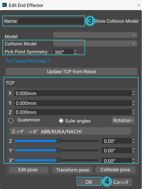
The functions of the buttons and options in the window are described as follows.
Name: name the end effector.
Model: select the added 3D model in the drop down menu.
Collision Model: select the added collision model in the drop down menu.
Pick Point Symmetry: used for selecting an optimal picking pose. This parameter is related to the way that the end effector picks the object, please set a proper value according to actual situation.
Update TCP from Robot: sends the TCP status of the real robot to Mech-Viz.
TCP: adjust the position of the end effector to the robot flange by adjusting the value of X, Y, and Z.
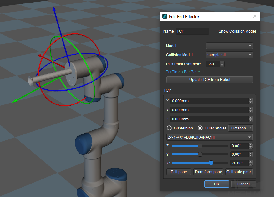
Quaternion and Euler Angles: quaternion and Euler angles are introduced to describe the rotation of the model.
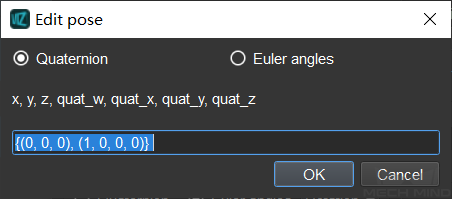
Edit Pose: enter quaternion or Euler angle directly to adjust the position of the end effector.
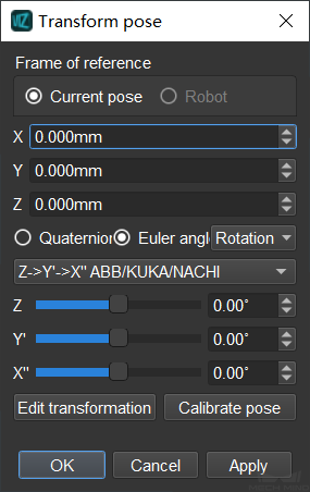
Transform Pose: transform current pose of the TCP to a new one.
You can adjust the position of the TCP by entering a value or scrolling the bar to adjust the X, Y, and Z coordinate.
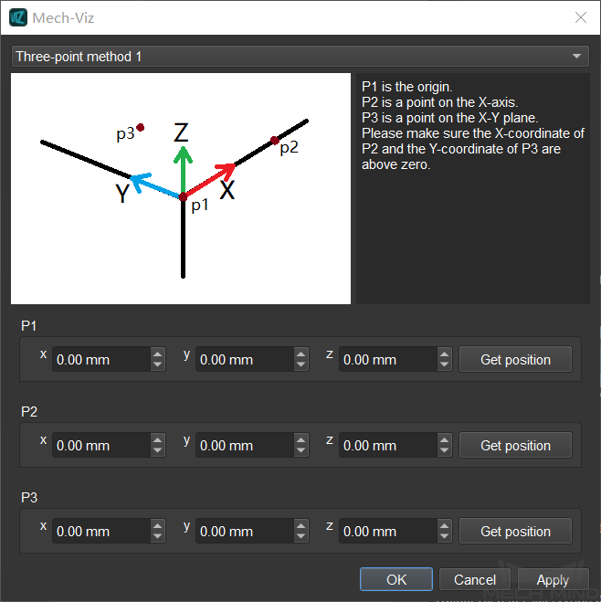
Calibrate Pose: set the coordinate of P1, P2, and P3 according to the instruction, and then calibrate the end effector pose with three-point method.
Define the TCP
In order to complete tasks such as picking, we usually say that the robot should move to a specific point in space, which actually means its TCP should move to that point.
After configuring the end effector, you will need to define the TCP.
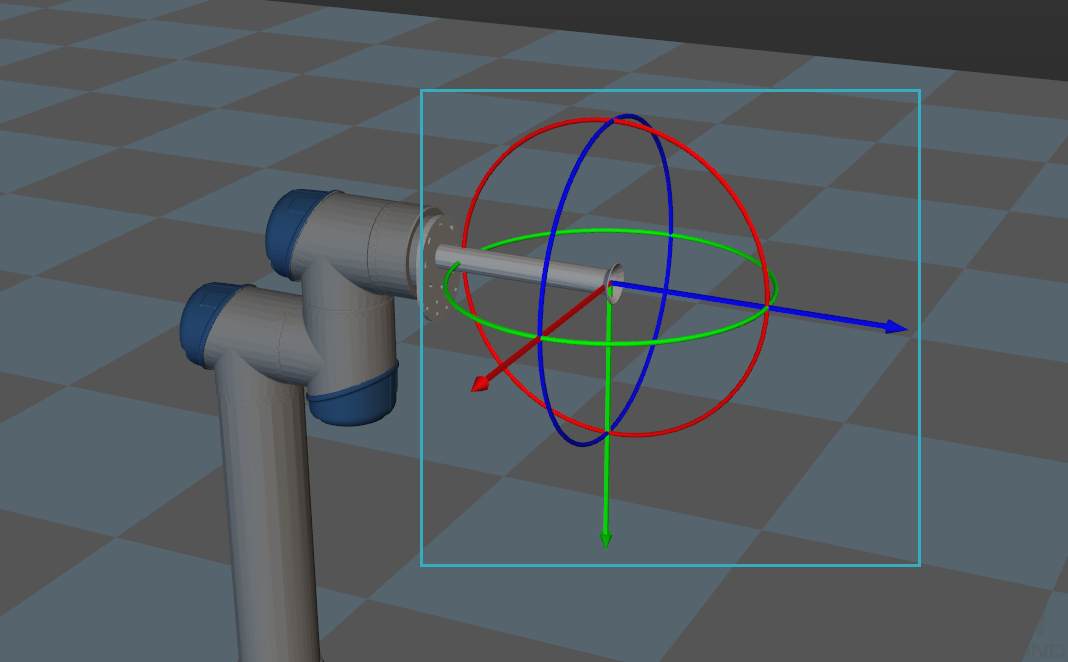
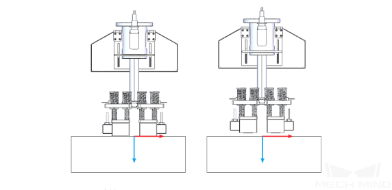
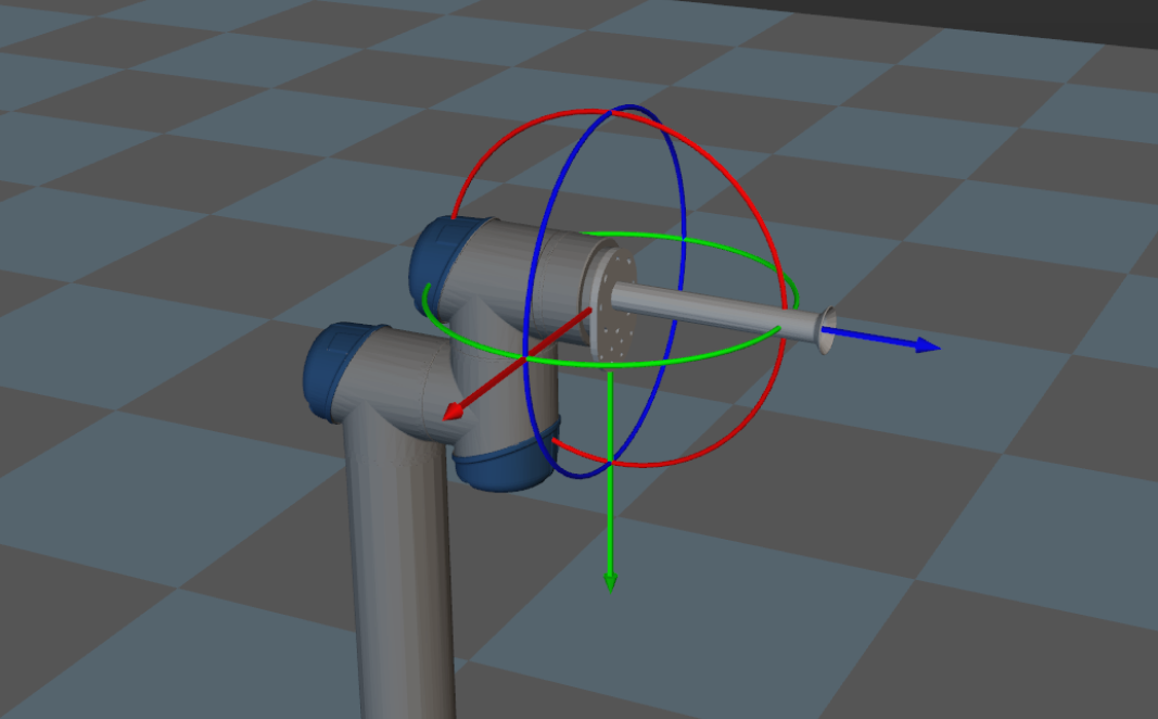
The TCP is represented by the center of the rotation manipulator at the end of the robot model. The position of the TCP by default is shown below.
Double click the TCP name in the End Effectors list to open the Edit End Effector winodw. Configure the parameters in the TCP panel to adjust the position of the TCP to the end of the end effector. After configuration, click on OK to save settings.

The correct position of the TCP after configuration is shown below.