Mech-Viz Quick Facts
Mech-Viz is a cutting-edge robot intelligent programming software that has a visualized and coding-free programming workspace and can make a simulation with one click. It has built-in intelligent algorithms such as path planning, collision detection, etc., and has an adapted robot library including models of many major brands.
As an integral part of Mech-Mind Vision System, Mech-Viz is used in conjunction with the other Mech-Mind software to realize intelligent production based on machine vision.
Overview of the Interface
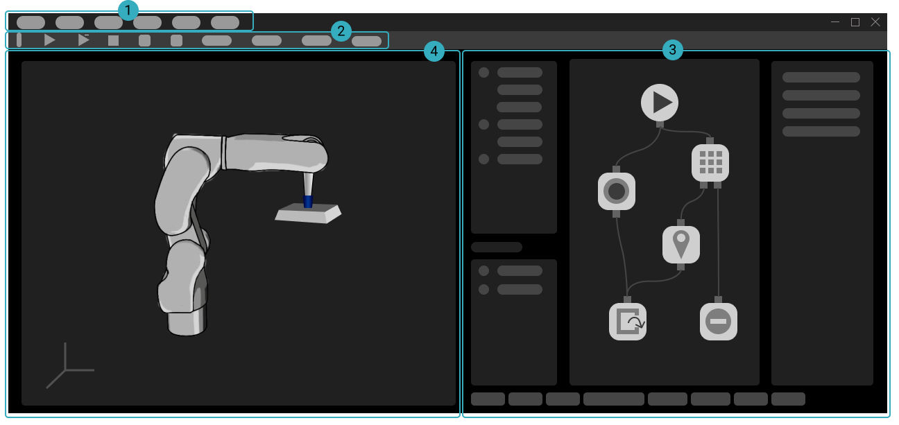
The interface of Mech-Viz consists of the following parts:
① Menu Bar: menus for basic features such as opening and saving a project, display adjustment, tools, settings, etc.
② Toolbar: provides options for simulating or running the project, connecting to the robot, adjusting robot velocity, etc.
③ Functional Panels: used to configure settings for an executable project, including the following 8 panels:
Workflow, Scene, Robot, Tools and Workobjects, Collisions, Plan History, Others, and Log
④ 3D Simulation Area: displays the robot path, collision detetcion results, workobject poses, point clouds, etc., during project simulation or execution.
3D Simulation Area
3D simulation area is a visualization window where you can edit the project. You will better understand various features in Mech-Viz if you are familiar with the the 3D simulation area.
Mouse Actions
The following mouse actions can be used to adjust your view in the 3D simulation area.
Rotate the view |
Hold left button and drag |

|
Display menu for quick view adjustments |
Right-click |

|
Pan the view |
Hold middle button and drag |

|
Zoom in or out |
Scroll |

|
Display Scene Objects
The 3D simulation area displays the following models in a project:
Robot model
Model of the robot tool
Models of scene objects
Ground
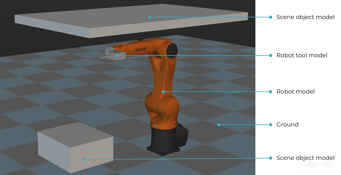
Note
The ground and the selected robot model are displayed by default for a blank project. Models of scene objects and robot tool must be added manually according to actual requirements.
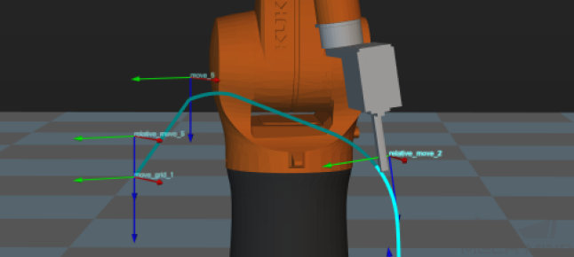
Display Planned Path
Whether moving the real robot or just the simulated robot, the 3D simulation area displays the planned path of the robot.
You can use the displayed path as an aid for adjusting the motion of the robot.
Display Received Vision Result
The vision result received from Mech-Vision is displayed in the 3D simulation area.
A vision result must include workobject poses and indices for the Mech-Viz project to run. A vision result may also include customized pose labels that indicate characteristics of the workobjects and point cloud of the scene and workobjects.

Display Detected Collisions
When planning a path for the robot, Mech-Viz detects whether the robot and/or robot tool collides with scene objects and workobjects. When a possible collision is detected, the two objects involved in the collision are displayed in light-blue and outlined with yellow in the 3D simulation area.
