Scene
When planning the path with Mech-Viz, it is not sufficient to use only one robot model in the 3D simulation area. In order to make the scene closer to the real scenarios and therefore facilitate path planning, collision detection, etc, the models of relevant devices (e.g. camera, base of the robot, etc) and objects (e.g. table, bin, etc) should be added to the scene.
This section covers the following topics:
Click on the Scene tab in the lower right corner to open the scene configuration panel.
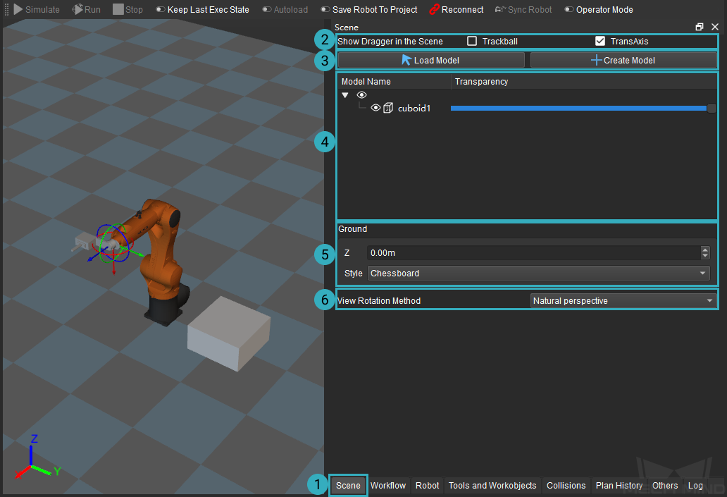
You can configure whether to show the dragger in the scene in ②, load or create a model in ③, configure the model in ④, configure the height and style of the ground in ⑤, and select a view rotation method in ⑥.
Show Dragger in the Scene
Select the object model in the scene, click Trackball or TransAxis will display the dragger of the object. Press and hold the Ctrl key, and then click and drag one of the axes to adjust the object pose, as shown below.

Load and Create Model
Click on Create Model to add a new object model in the scene. Set the object name, type, and side lengths in the Create New Model window.
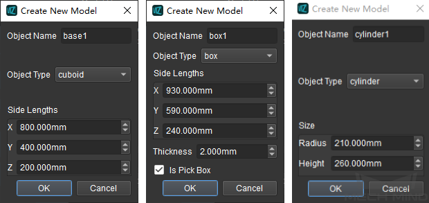
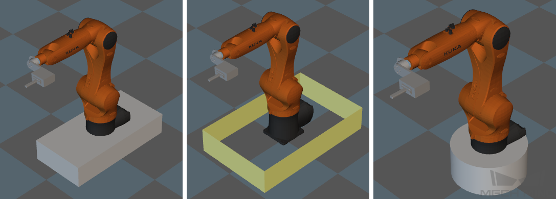
The created models are shown below: cuboid1 on the left, box1 in the middle and cylinder1 on the right.
Attention
As for the object type, a cuboid is solid and a box is hollow.
If Is Pick Box is checked when the object type is selected as “box”, the color of the box will be different from other objects.
The pose of the object model cannot be specified when creating the model. Please go to to adjust the object pose later.
If you need to use a model from other existing projects, click on Load Model to load an existing model (support STL, OBJ, DAE and other formats). Select the model you need in the pop-up window and click on Open.
Attention
After loading the model, sometimes the model may be too large for the scene. It is because of the transformation between meter and millimeter. Please double click on the model, select Model Affine in the Edit 3D Object window and change the scale into 0.001.
If the collision model is in OBJ format, please read Notes for OBJ Collision Models first to avoid collisions.
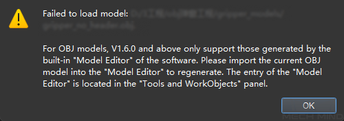
If the import OBJ scene model is illegal, an alert window as shown below will pop up. Please follow the instructions in the pop-up window and re-export the model from the model editor.
Copy, Paste, Delete, and Rename the Model
Right click on the added model and you can choose to copy, paste, delete, and rename the model in the context menu.
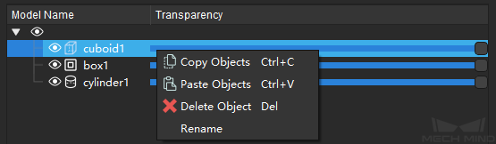
The shortcuts are shown below.
Options |
Shortcuts |
Copy |
Ctrl+C |
Paste |
Ctrl+V |
Delete |
Delete |
Multi-select |
Ctrl |
Undo |
Ctrl+Z |
Restore |
Ctrl+Y |
Tip
When you copy and paste an object, the sub-objects will be copied and pasted as well.
After copying an object, if you would like to make it appear in the same class as the parent object, please click at the blank space of the model configuration area to unselect any object first, and then press Ctrl+V to paste the object. If you would like to make the copied object as a sub-object of a certain parent object, please right click on the parent object and select Paste Objects.
The copies of the object will be numbered in sequence.
Edit Model
After loading or creating a model in the scene, you may need to adjust the pose of the object. Please double click on the model to open the Edit 3D Model window.
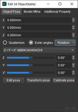
Object Pose
Adjust the object pose in the object pose tab.
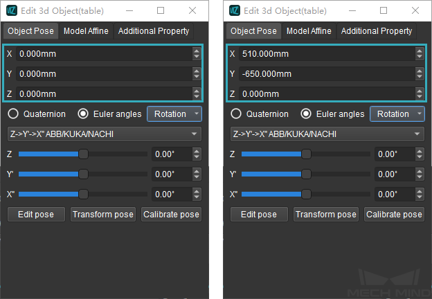
X, Y, Z: adjust the position of the object to the robot.
The figure below demonstrates the parameters before and after adjusting.
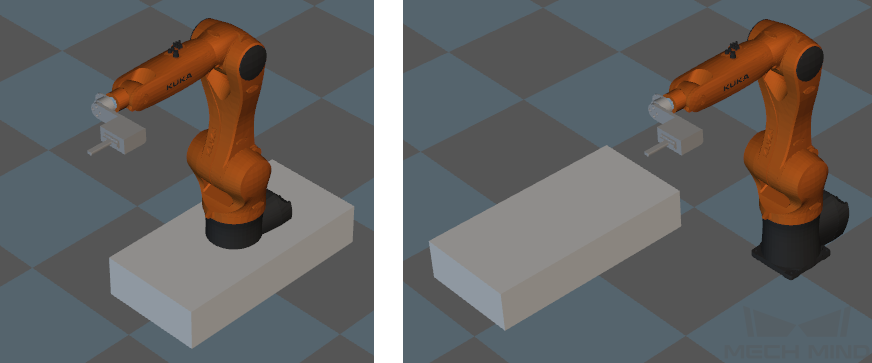
The figure below demonstrates the scene before and after adjusting.
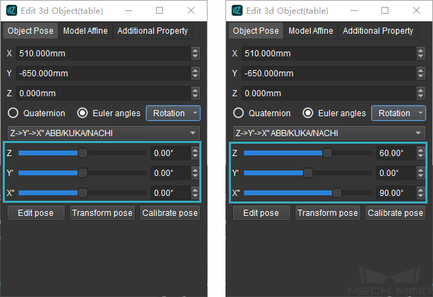
Quaternion and Euler angles: adjust the rotation of the object to the robot. When Euler angles is checked, please select the sequence of the rotational axis.
The figure below demonstrates the parameters before and after adjusting.
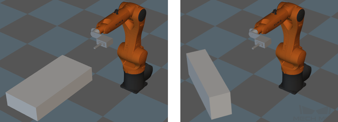
The figure below demonstrates the scene before and after adjusting.
Rotation: includes options as auto align, edit rotation (enter a quaternion), 90° Clockwise Around X, 90° Clockwise Around Y, etc.
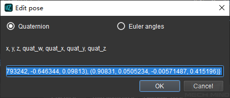
Edit Pose: enter a value directly to edit the pose. Please note that the unit used here is meter.
Transform Pose: transform the current pose to a new one. A new coordinate system will be established based on the current pose. Therefore, this option is suitable for adjusting complex poses.
The figure below demonstrates the parameters before and after adjusting.
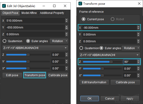
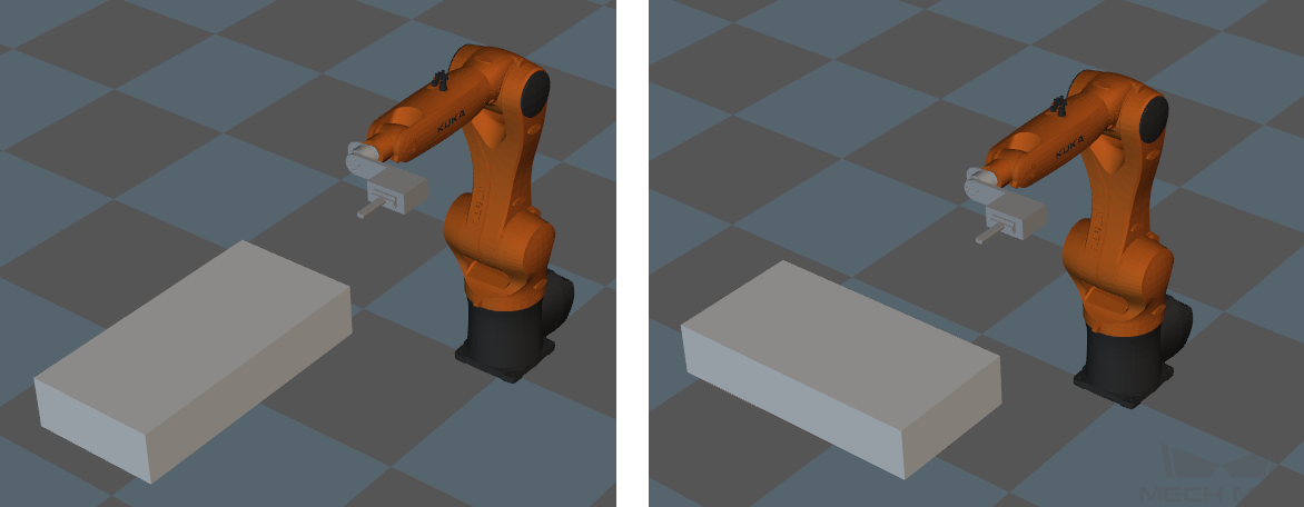
The figure below demonstrates the scene before and after adjusting.
Calibrate Pose: set the coordinate of P1, P2, and P3 according to the instruction, and then calibrate the end effector pose with three-point method.
Model Affine
You can adjust the object pose and apply an affine transformation in the Model Affine tab.
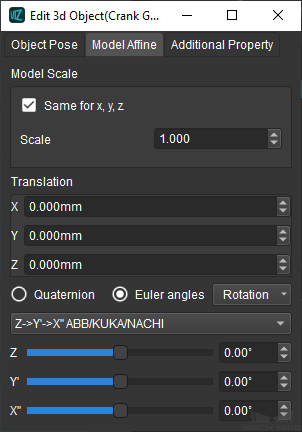
Model Scale: scale the model by setting the model scale. If you need to scale the model in the X, Y, or Z-direction independently, please uncheck Same for x, y, z and enter the scale ratio in the X, Y, or Z-direction respectively.
Attention
The Model Affine tab is only available for loaded models.
Additional Property
Set the side lengths and other parameters in the Additional Property tab.
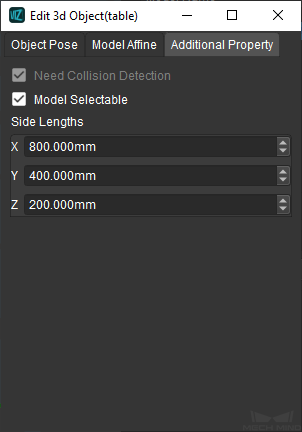
Need Collision Detection: checked by default.
Model Selectable: check to make the model selectable.
Side Lengths: enter the side lengths of the object.
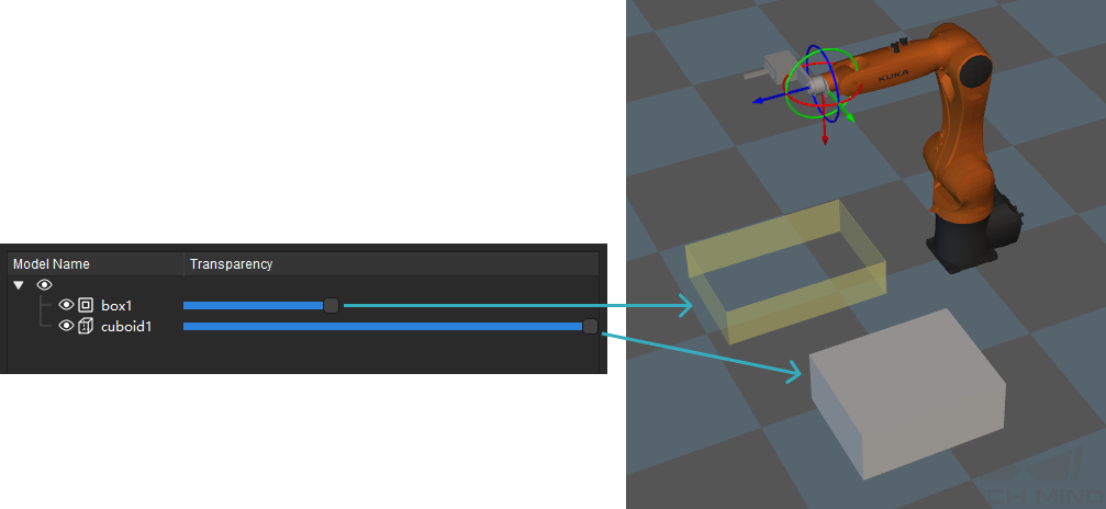
Adjust Transparency of the Model
It may be distracting when there is too much objects in the scene or the objects are overlapping. In such case, you can configure to whether display the model or not and adjust the transparency of the model.
Click on the icon on the left to display or hide the model. The icon ![]() indicates that the model is displayed, and
indicates that the model is displayed, and ![]() indicates that the model is hid.
indicates that the model is hid.
Configure the Height and Style of the Ground
You can set the height and style of the ground in the Ground tab.
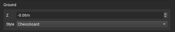
Z: set to adjust the height of the ground, either a positive or negative number is feasible.
Style: available options include Chessboard, Grid, Gridlines, and None. It is recommended to select the first two styles.
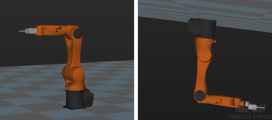
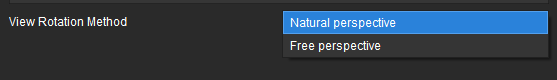
View Rotation Method
View Rotation Method includes Natural perspective and Free perspective. You can click and drag to view the scene. For both perspectives, the center of the view is the center of the coordinate system. Under natural perspective, the maximum degree of rotation about the X-axis or Y-axis is 180°, and the maximum degree of rotation about the Z-axis is 360°. Under free perspective, the the maximum degree of rotation about either X-axis, Y-axis, or Z-axis is 360°.
The figure on the left gives an example of scene under natural perspective, and the figure on the right gives an example of the scene under free perspective. The scene on the right cannot be viewed under natural perspective.