General Process for Using Model Editor
The general process for using the model editor mainly includes the following steps:
Import the Reference Model
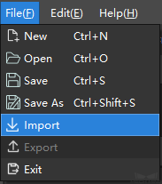
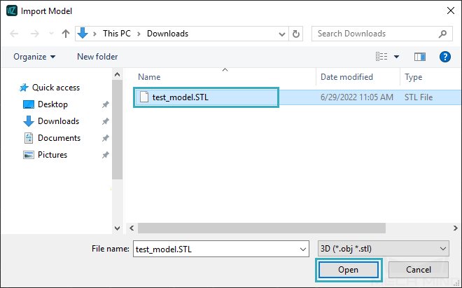
Go to in the menu bar, or click on the Import button in the Reference Model panel, and then select the needed model file in the pop-up window, and click on Open.
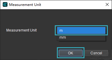
Select the proper unit (m or mm) of the model in the pop-up Measurement Unit window, and then click on OK.
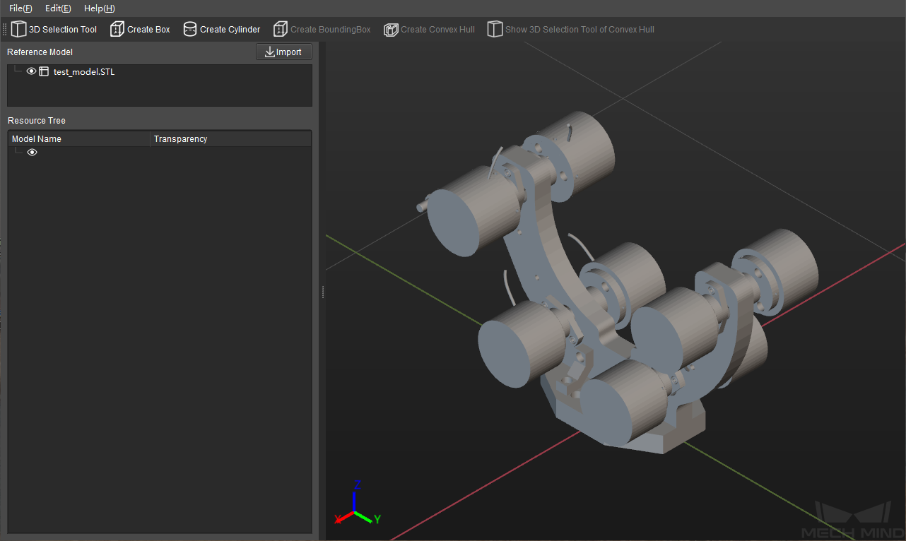
The model will be displayed in the editing workspace if it is imported successfully, as shown below.
Select Vertices and Create Convex Hull
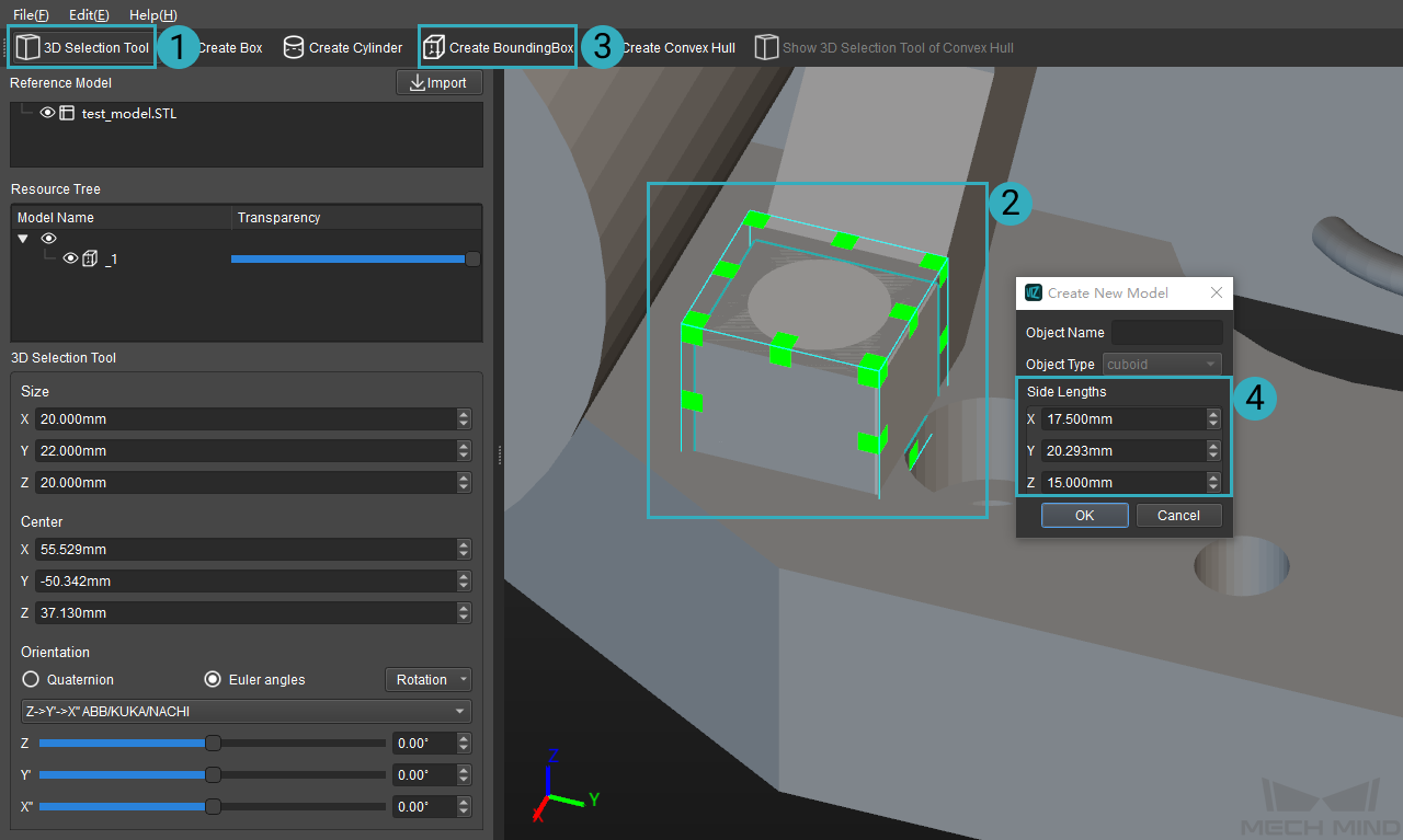
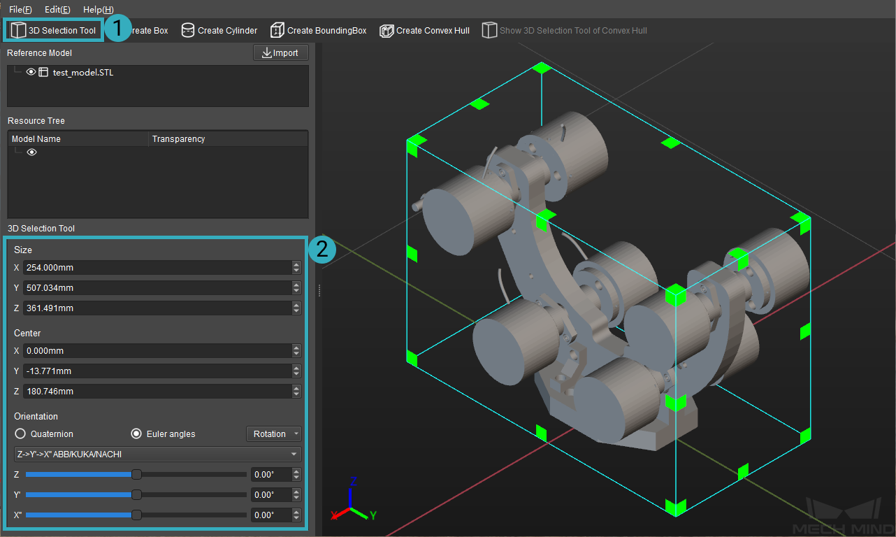
Click on 3D Selection Tool to create a cuboid-shaped selection frame. You can adjust the parameters in the panel on the left to adjust the dimensions and position of the 3D frame, and you can also use the mouse and keyboard to adjust its dimensions and position more intuitively.
Hint
Press and hold the Ctrl key, hold down the left mouse button and drag the vertices of the 3D frame to adjust the dimensions.
Press and hold the Ctrl key, hold down the left mouse button and drag the surfaces of the 3D frame to adjust the position.
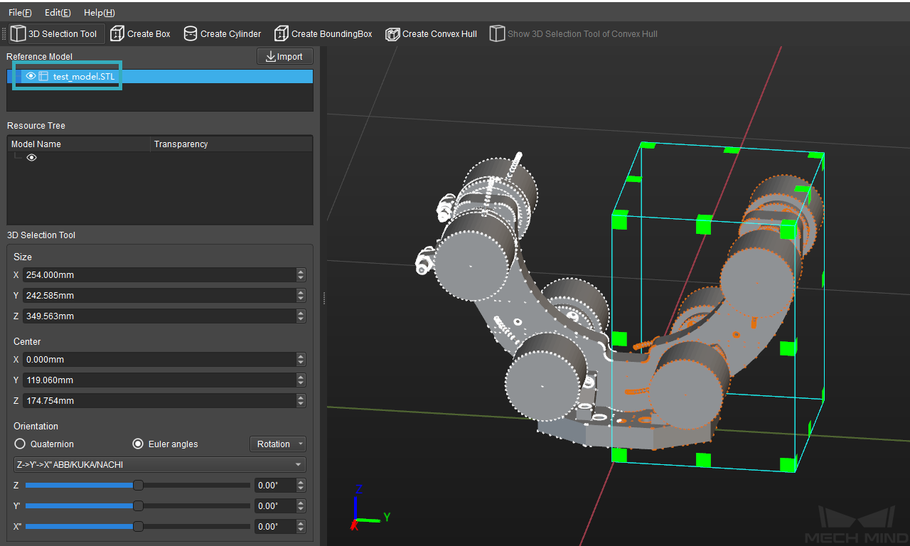
Click on the name of the model in the Reference Model panel, the vertices of the model will be displayed in the editing workspace. The vertices inside the 3D frame will be displayed in orange, and the vertices ourside the 3D frame will be displayed in white, as shown below.
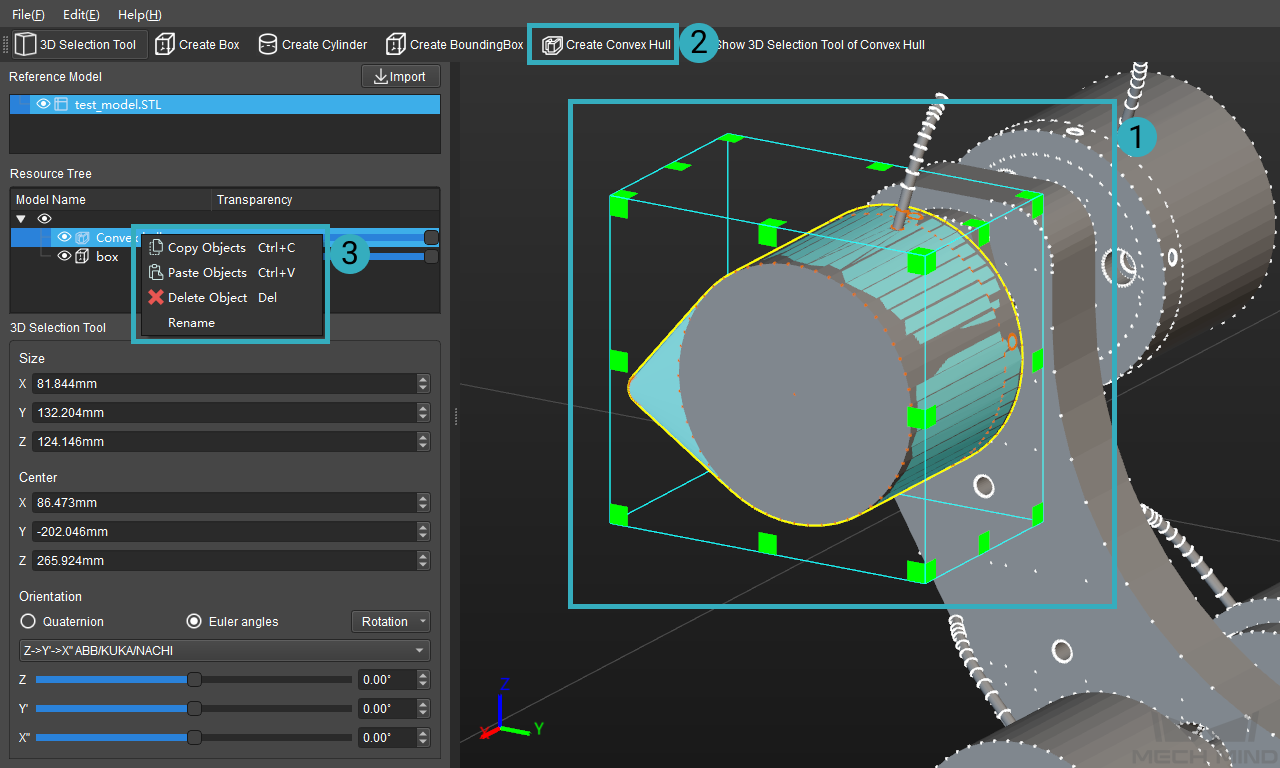
Adjust the position and dimensions of the 3D frame to select certain part of the model, and then click on Create Convex Hull to simplify the part. The created convex hull will be displayed in the Resource Tree panel. Right click on the name of the convex hull, and you can copy, paste, delete, and rename it by selecting the option you need in the context menu.
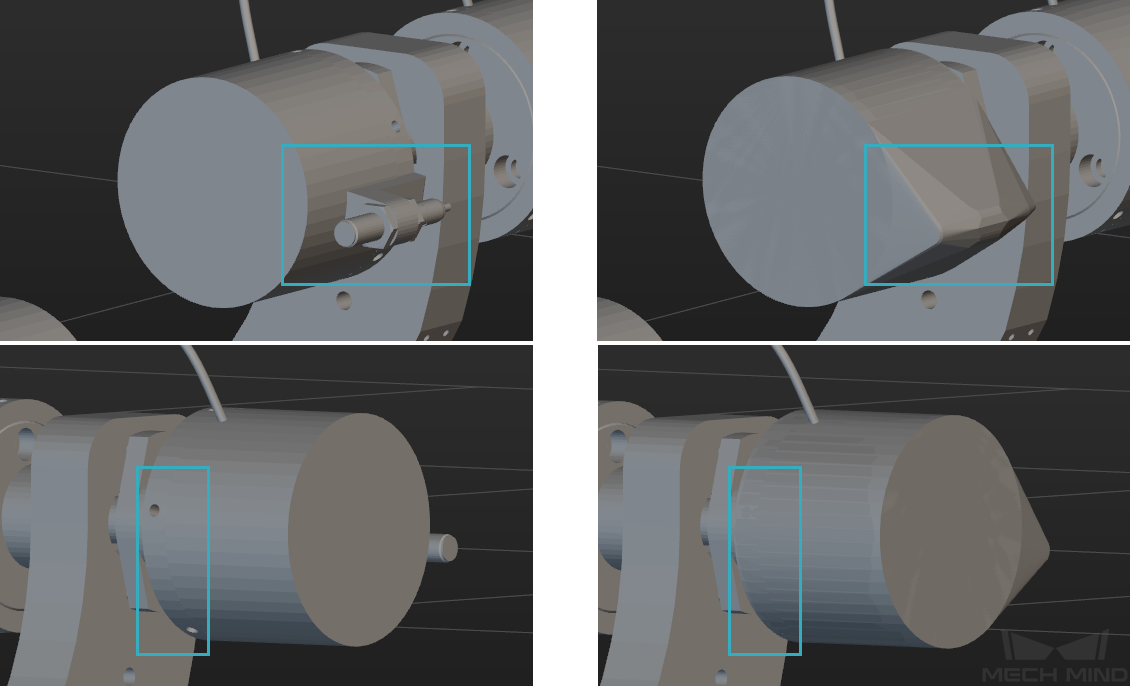
The figure below shows an example of a part of the model before and after being simplified.
Hint
Please refer to STL Models Simplification and OBJ Models Simplification for basic methods of simplifying models.
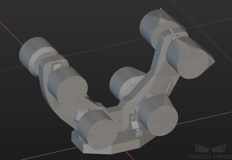
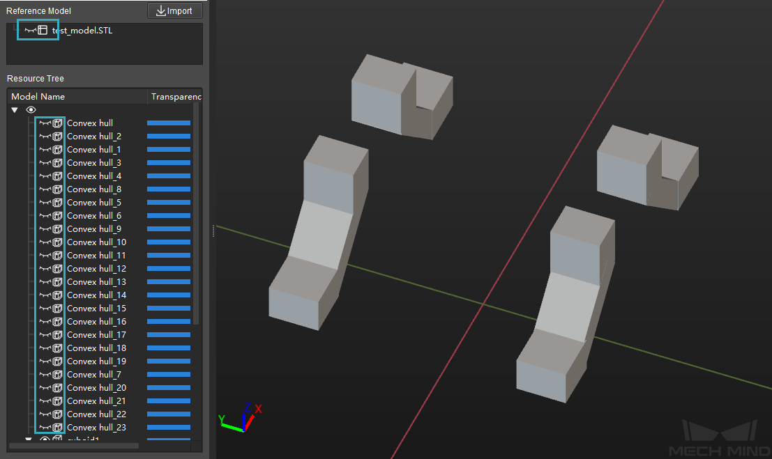
Create more convex hulls to simplify the model, as shown below.
Create Geometric Solids
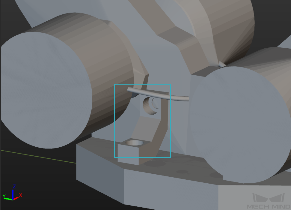
Although it is convenient to create convex hulls with 3D selection tool to simplify the model, some parts with complex structure of the model cannot be selected with a 3D cuboid-shaped frame in a simple way, as shown below.
For such parts with complex structures, you can create some geometric solids with similar shape to replace them. The detailed instructions are as follows.
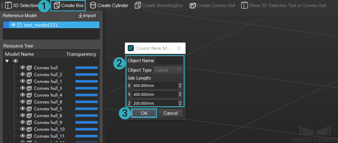
Click on Create Box, name the object and set the side lengths in the pop-up Create New Model window. The side lengths can be an approximate one, for you can fine-tune them in the following steps. Click on OK to save the settings.
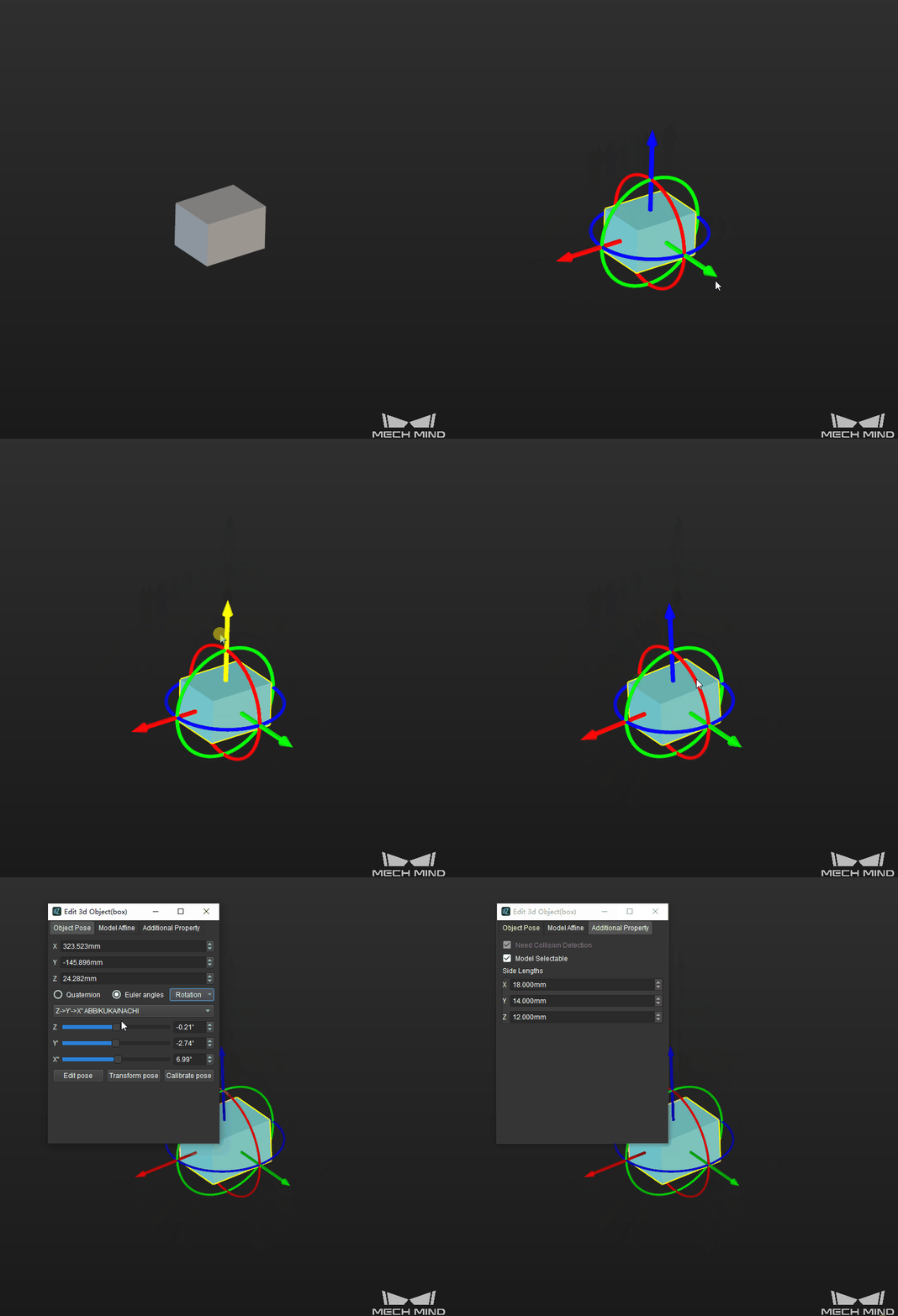
As shown below, click on the cuboid to display the dragger. Press and hold the Ctrl key, and drag the dragger with left mouse button to translate and rotate the cuboid. Double click on the cuboid, and you can configure relevant parameters of the cuboid in the Edit 3D Object window.
Hint
The way to configure the parameters of the created geometric solids in the Edit 3D Object window is the same as that of the scene objects. Please refer to Scene for detailed information.
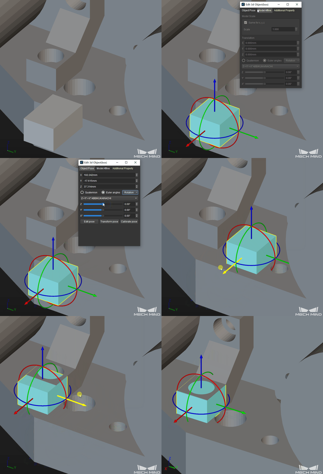
Drag the cuboid to the part with a hole on it. Adjust the side lengths and position of the cuboid to make it almost the same size as the part to be filled and therefore fill the hole.
Fill other small holes on the model in the same way. The final result is shown below.
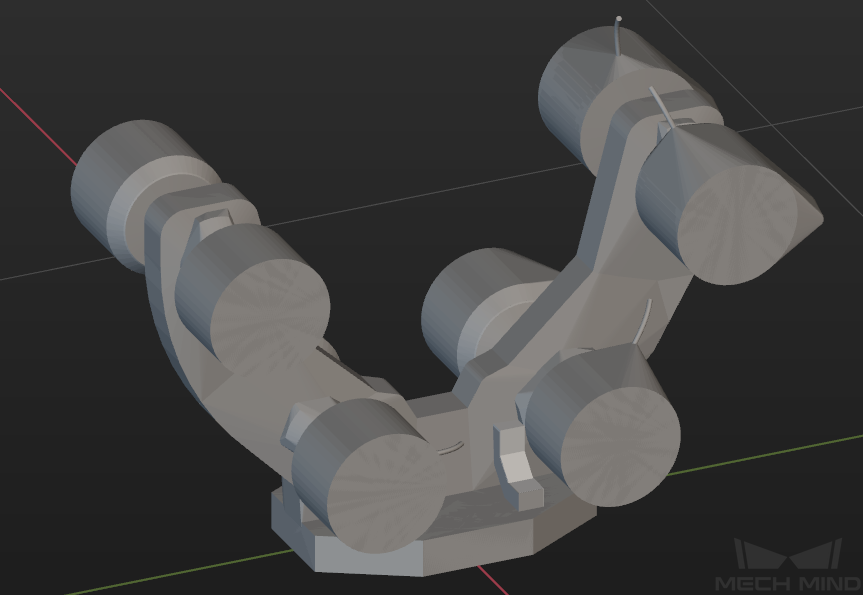
The figure below is an example of the simplified model after the complex parts have been filled with geometric solids.
Export the Model and Save the Project
Export the Simplified Model
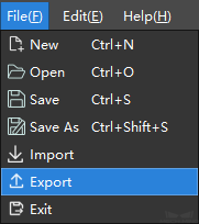
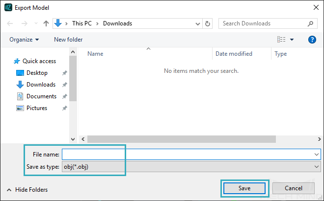
Select in the menu bar, select a directory to save the model, name the model and select the file type (STL or OBJ), and then click on Save to export the simplified model.
Hint
The exported model can be added as an end effector model or collision model. Please refer to End Effector Configuration for detailed instructions.
Save the Project
In order to facilitate further editing on the simplified model, you can save the editing project as well. The saved project is in M3D format, which contains all editing history, and you can open it in the model editor and re-edit the model.
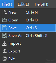
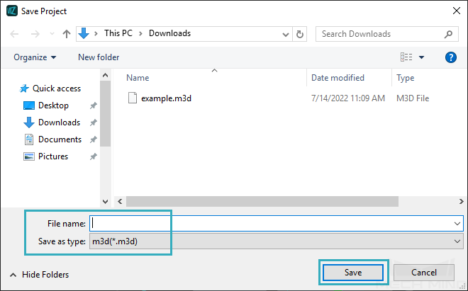
Select , select a directory to save the model, name the model and then click on Save to save the project as a M3D file.
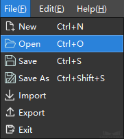
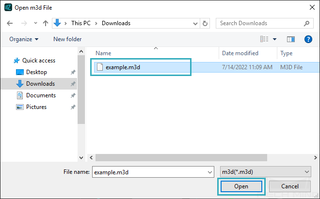
If you need to re-edit the model, go to , select the M3D file in the pop-up window and click on Open to open the project.
Hint
After re-editing the model, clicking on Save will save all changes to the existing M3D file, while clicking on Save As will save the file as a new M3D file, and you can specify a new directory to save it.
