Vacuum Gripper Configurator
Vacuum gripper configurator supports to configure vacuum grippers of rectangular shape, one block, multi-blocks, and in a single row. Vacuum grippers of round shape, multi-blocks, or in multiple rows are currently not supported.
After configuration, you can use the configuration file in corresponding Tasks and open the configuration file in the vacuum gripper configurator as well.
Hint
Please configure according to the actual vacuum gripper of the robot.
For vacuum grippers that are horizontally installed, multiple blocks structure and DI check are not supported.
Introduction of the Interface
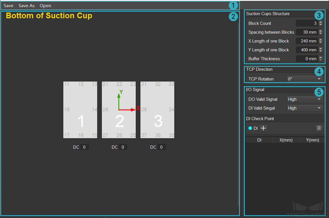
The main interface of vacuum gripper configurator consists of 5 parts:
Menu Bar
Visualization Area
Vacuum Gripper Configuration Panel
I/O Signal Configuration Panel
TCP Direction Configuration Panel
Vacuum Gripper Configuration
Configure the structure of suction cups
Set the Block Count, Spacing between Blocks, X Length of one Block, and Y Length of one Block in the Suction Cups Structure, and the structure of suction cups on the bottom side will be displayed in the Visualization Area in real time, as shown below.
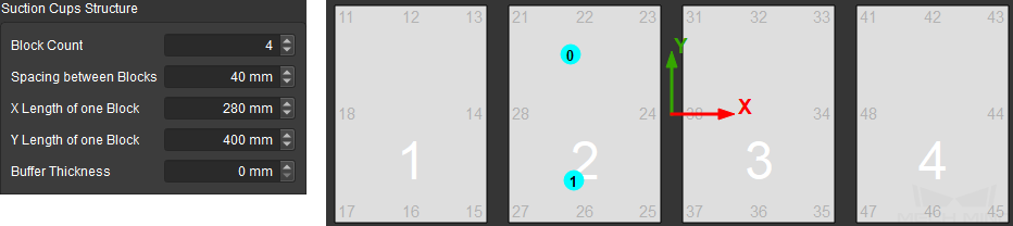
Buffer Thickness is used to set the thickness of the buffer used for collision detection. One side of the buffer is pressed against the plane where the TCP is. The buffer thickness of the operative vacuum gripper block will be the same as the set thickness, while the buffer thickness of inoperative vacuum gripper block will be 0 and it will not be included in the collision detection.
Hint
For multiple blocks that share one DO, they can be viewed as a whole block. You can create one large block to represent them in the vacuum gripper configurator.
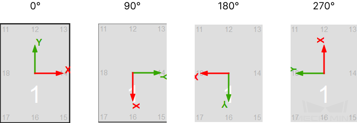
Configure TCP direction
Different TCP directions correspond to different reference frames, as shown below. Please select according to actual needs.
Configure I/O signal
Please choose between High and Low according to the actual voltage level of the DI and DO.
Configure DI check point
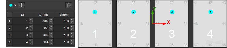
Click on + in the DI Check Point Panel to add DI check points. The default value of the DI is 0 and the check point is located in the center of the vacuum gripper.
Modify the name of the check point in the DI column. Drag the check point to a proper position, and the coordinates of the check point will be displayed in the DI Check Point Panel in real time. Also, you can modify the coordinates of the check point to move it as well, as shown below.
If you need to delete the check point, select it and click on
 .
.Set the number of DO
Enter the number in the box under the corresponding vacuum gripper in the visualization area.
Save or Utilize the Configuration File
After configurtaion, click on Save or Save As to save the JSON file to a specified directory.
Click on Open to open an existing vacuum gripper configuration file in JSON format.