Common problems about vision
Description for common problems about vision
This chapter mainly list the proper methods for recognition of different workpieces and inspection requirements, etc., to improve the recognition accuracy and takt time.
Select features for 3D matching
For a workpiece, such as a sphere, after moving a distance of 1 mm in any direction, the sphere coincides with the original sphere badly. For a plane, after moving 1 mm along the X axis or Y axis, the degree of coincidence between before and after the moving is greater. Therefore the sphere is more restricted than the plane. So for different workpieces, a template can be made according to the degree of restriction, the complete template shall be selected for the more restricted objects, while the edge feature shall be selected for the less restricted objects. Figure 2.1 shows the degree of restriction of the simplified workpiece.
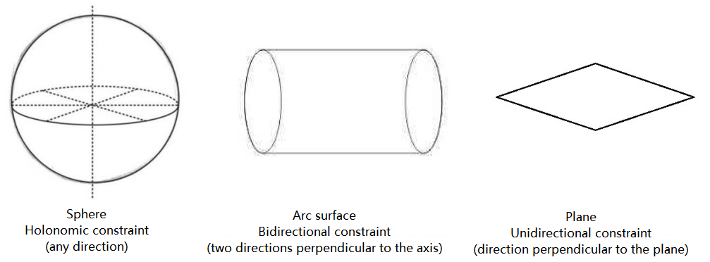
Figure 2.1 Restriction of the simplified workpiece
3D matching for reverse and rotating poses
The shape of the workpiece basically include two types: asymmetry and symmetry. Symmetric workpieces include:
Axisymmetric (simplified as rectangular);
Centrosymmetric (simplified as square);
Continuous symmetry (simplified as circle) etc.
For symmetric workpieces, the matching errors caused by symmetry can be reduced by the following methods:
1> Select the geometric center with symmetry as the grasping point on the point cloud template;
2> Select the axis of symmetry:
Axisymmetric workpiece: select the coordinate axis along the axial direction as the axis of symmetry, and set the symmetry to 180 degrees in 3D Fine Matching; as shown in figure 2.2 (left: axis of symmetry; right: parameter settings).
For Centrosymmetric workpiece: select the coordinate axis along any axis of symmetry as the axis of symmetry, and set the symmetry to 90 degrees in Step (local matching).
For Continuous symmetric workpiece: select the rotation axis as the symmetry axis, and set the symmetry to any angle in 3D Fine Matching . If the angle is small, the matching accuracy can be increased, but the matching time will increase; otherwise, the matching accuracy and the matching time may decrease. As shown in figure 2.3 (left: axis of symmetry; right: parameter settings).

Figure 2.2 Axisymmetry - crankshaft
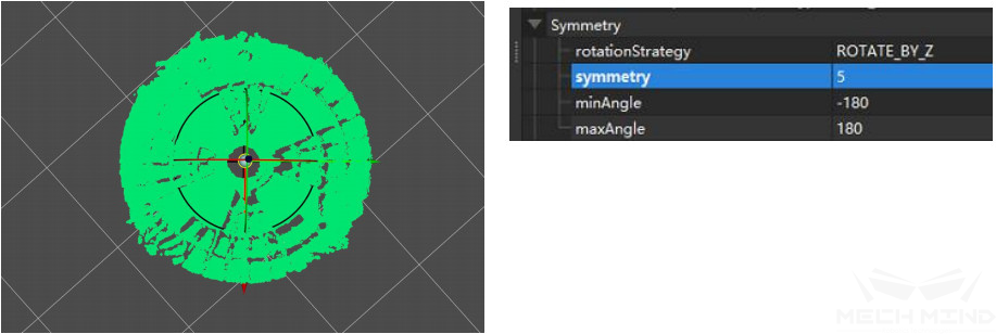
Figure 2.3 Continuous symmetry - roller
3> Set weights:
For Axisymmetric workpiece: if it is pure axisymmetric, it is unnecessary to set the weight; otherwise for crankshaft-like workpiece, its two ends do not have symmetry. Therefore, in order to avoid mismatches caused by rotation matching, the features of both ends should be treated as weight templates and set in the 3D Fine Matching weight parameter. The template is shown in figure 2.4 (left: Symmetric matching template; right: Symmetric weight template).
For Centrosymmetric workpiece: the weight setting is consistent with the axisymmetric workpiece.
For Continuous symmetric workpiece: the weight setting is consistent with the axisymmetric workpiece. As shown in figure 2.5 (left: Continuous symmetric matching template; right: Continuous symmetric weight template).
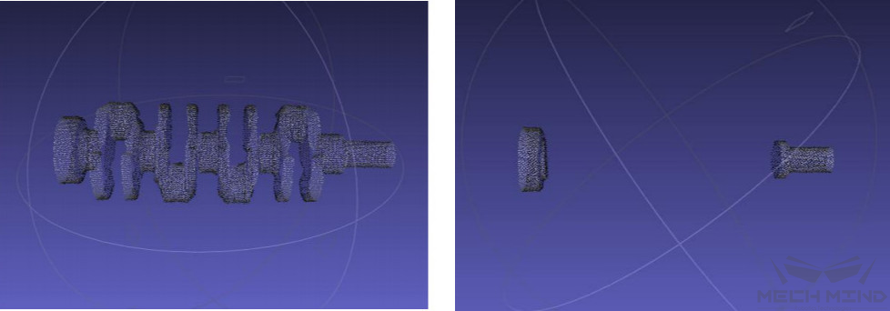
Figure 2.4 Symmetric matching template - weight template
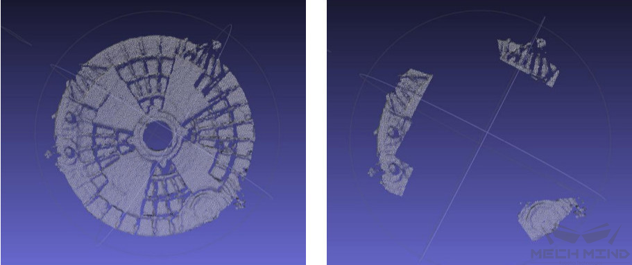
Figure 2.5 Continuous symmetric matching template - weight template
No results for getting highest-score poses in 3D multi-matching
When performing multiple matching (multiple matches are included in a project) to get the highest matching pose, sometimes there will be no results. The solution is as follows:
1> Make sure the value of confidence in 3D Fine Matching is 0 (To avoid the problem that the number of input parameters in Get Highest Score Result does not match due to a certain matching score of 0).
2> Make sure that the number of 3D Coarse Matching outputs is 1 (Generally it is 1, if there are multiple outputted matching poses, there is a chance that the number of outputted poses in two ways are different).
No results for 2D matching
During 2D matching, sometimes there will be no output results. At this time, check the size of template and check the depth roi and 3d roi;
1> Check the size of template;
Make sure that the size of template set by Step Read Object Dimensions is consistent with the size of the actual workpiece;
When the size is consistent, increase the threshold maxMeanDistanceError of 2D Matching ;
Adjust the expansion parameter of the outermost mask to expand the range of 2D matching input ROI;
Setting in Step is shown as in figure 2.6 (left: Read Object Dimensions; right: 2D Matching ).
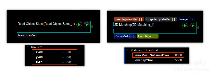
Figure 2.6 Settings of parameters related to 2D matching
2> Check depth roi and 3d roi: mainly to avoid that objects are out of the matching range.