3D Fine Matching
Function
Accurately match the point cloud model with the original point cloud, and outputs more accurate poses of target objects.
Hint
Please refer to Generate Point Cloud Model to create a point cloud model.
Sample Scenario
This Step performs fine matching based on the matching results of 3D Coarse Matching, and outputs more accurate object poses, which can be used as pick points.
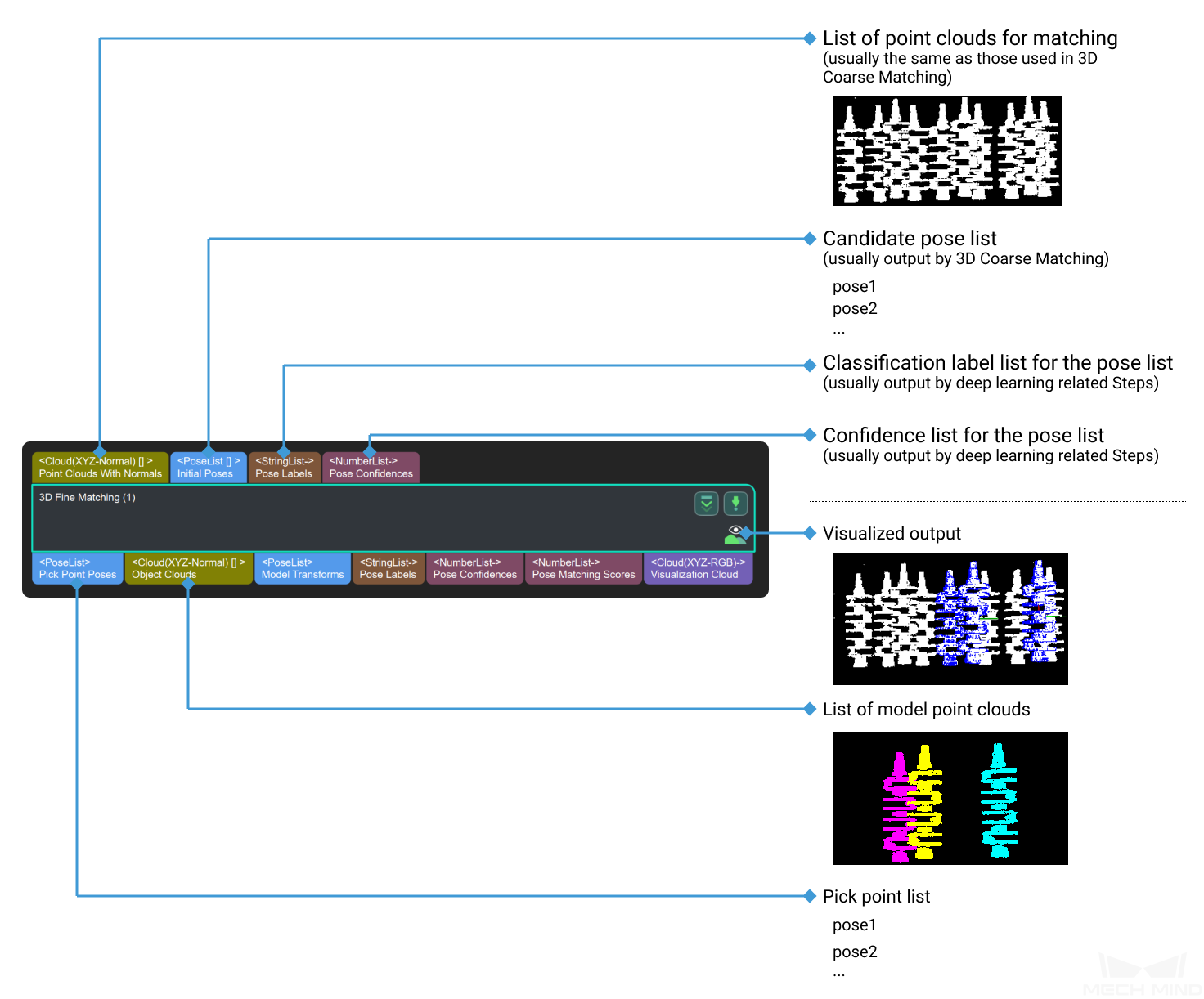
Input and Output
Parameters
The Parameters Tuning Level, found under Execution Flags under, sets the extent of completeness that the parameters are displayed for adjustment.
Options:Basic,AdvancedDefault setting:Basic
Basic: Only commonly used parameters are displayed for adjustment.
Advanced: All parameters are displayed for adjustment.
Advanced parameters are marked with ☆ below.
Key parameters |
Introduction |
|---|---|
Model and Pick Point |
Set the model file path and the geometric center file path |
Cloud Orientation Calculation |
Choose the calculation method of point cloud orientation |
Correspondence Settings |
Select the method to match the point cloud model with the object point cloud |
Sample Settings |
Set the details of sampling the point cloud |
Symmetry Settings ☆ |
Tell the matching algorithm the symmetricity of the objects |
Model Weight in Validation ☆ |
The weight added to object parts with obvious features to facilitate matching |
Validation Settings |
Settings on matching result validation |
Output Settings |
Settings on matching result output |
Acceleration Settings ☆ |
Whether to use GPU to accelerate the running |
Results Visualization |
What parts of the results to visualize |
Parameter Tuning
Model Settings
- Model Selection
Click on ▼ to select a point cloud model saved in the model gallery (the \resource\3d_matching directory under the project folder).
Once you select a point cloud model, its path and the path of its geometric center file are automatically displayed in Model File and Geo Center Point File below.
Note
The drop-down list of ▼ only displays the folders containing point cloud models and the associated geometric center/pick point files in the model gallery.
You can use Matching Model and Pick Point Editor to easily generate, edit and save point cloud models and the corresponding geometric centers/pick points.
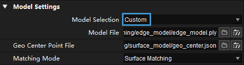
- Model File
to select a point cloud model file in PLY format.
- Geo Center Point File
Note
If the point cloud model file and geometric center file you selected are not located in the same folder in the model gallery, the display of Model Selection changes to Custom.
Cloud Orientation Calculation
- Point Cloud Calc Mode
- Default setting:
OriginOptions:Origin,StandardMode,EdgeTangent,EdgeNormalDescription: The above options represent four methods for calculating the direction (normal) of the point cloud model required for the matching algorithm. The normal of the point cloud is perpendicular to the image plane of the depth map on which the point cloud is generated.Origin: Directly obtain the normal from the point cloud model when the file contains the normal of the point cloud model.StandardMode: Select a target, search for the k points closest to the target in the vicinity of the target, and find the minimum feature vector as the normal by principal component analysis.EdgeTangent: Calculate the tangent at the edge of the point cloud model, and take the tangent as the normal. This method can distinguish different objects whose outer contours are mirror images of each other.EdgeNormal: Calculate the normal at the edge of the point cloud model. This method is recommended for relatively flat objects.
Note
When using
EdgeTangentorEdgeNormal, please ensure that each edge point cloud does not contain multiple objects (each object’s point cloud should be separate and no object should overlap in the point cloud). - Number of Searching Points
- Default setting:
10Description: This parameter is forStandardModementioned above. It sets the k value, i.e., the number of points in the vicinity of the target to search for. The minimum value is1. The larger the value, the more accurate the result, the slower the computation.
Correspondence Settings
Default setting:GMMOptions:GMM,nearest-neighborDescription: Select the method to match the point cloud model with the object point cloud. The point cloud model will be moved and rotated within the set range to match the object point cloud.Applicability: In most scenarios, GMM has better anti-interference performance and higher matching speed, so it is generally recommended; in rare cases, when GMM cannot meet the requirement, nearest-neighbor can be selected.Please see Settings under GMM and Settings under Nearest-Neighbor below for parameter adjustment instrutions of the two methods.
The figure below is an example of a comparison between the input point cloud and the visualized output matching results via nearest-neighbor.
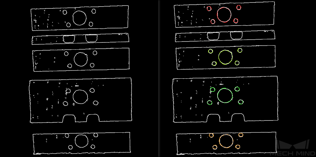
Figure 1. Input/output of matching via nearest-neighbor
Settings under GMM
- Matching Mode
- Default setting:
StandardOptions:HighSpeed,Standard,HighPrecisionDescription: please select based on the accuracy and speed requirements.HighSpeed: The fastest but less accurate.
Standard: Relatively stable.
HighPrecision: The most accurate but slower.
- Number of Iterations
- Default setting:
30Description: Iteration refers to iteratively running a specific instruction until the conditions are met. The number of iterations refers to the number of repetitions of instruction running in this process. The parameter set here is the upper limit of the number of iterations. The larger the value, the greater the number of times of matching calculations, the longer the running time, the higher the accuracy. - Standard Deviation
- Default setting:
0.005 mDescription: This value is a measure of the expected deviation of the matched pose of the model from the actual pose of the object after 3D Coarse Matching. The closer the expectation to the actual value, the faster the calculation can be, but a higher Standard Deviation will lead to less accurate matching results. Normally, this value will be no greater than0.01 m. | Example: The figure below is a comparison between matching results when Standard Deviation is0.04 mand0.01 mrespectively.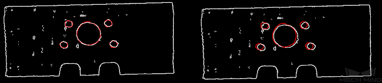
Figure 2. Comparison of results under different Standard Deviations
- Standard Deviation Update Step Number
- Default setting:
3Description: During the matching, the standard deviation gradually decreases, until it reaches the Minimum Standard Deviation. The value of this parameter is the number of times the standard deviation is updated in the matching algorithm. Normally this parameter does not need adjustment.
- Apply Weight in Iteration
- Default setting:
FalseOptions:True,FalseDescription: If set toTrue, the weight of the points in the point cloud model will be used in the iteration to facilitate the matching.Please see Weight in Point Cloud Matching for why and how weight works.
- Speed Up on Large Object Quantities
- Default setting: DisabledDescription: It is recommended to enable this option if there is a large number of objects in the scene. If this option is enabled, the Step will perform faster when there is a large number of objects. However, if the number of the objects is small, the processing speed of the Step may be slowed down.
Settings under Nearest-Neighbor
Iteration Settings
- Number of Iterations
- Default setting:
30Description: Iteration refers to repeatedly running a specific instruction until the conditions are met. The number of iterations refers to the number of repetitions of instruction running in this process. The parameter set here is the upper limit of the number of iterations. The larger the value, the greater the number of times of matching calculations, the longer the running time, the higher the accuracy. - Nearest Point Search Radius
- Default setting:
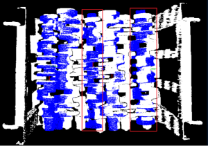
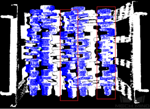
0.01Minimum:0.001Description: It adjusts the search radius of the closest point, its unit is m, and its value should correspond to the input initial pose deviation, i.e., the pose deviation after 3D coarse matching. If the deviation is large, the search radius should be large. The value of this parameter should be no lower than0.001; otherwise, some sparsely distributed points of the object point cloud may not be matched to their nearest points in the point cloud model, thus affecting the output result.Example: When the initial deviation is large while this parameter is set to the minimum value0.001, the matching will be incomplete. When this parameter is increased to a larger value like0.01, the search radius increases, and the matching will be comparatively complete.
Below are two parameters that set the standard by which the matching iteration ends. The iteration ends when either of the standards set by MSE Threshold and Window Size is met.
- MSE Threshold
0.001Description: It adjusts the threshold of the mean square error (MSE), which is a measure of the closeness of the matching. The MSE is recorded and compared with the MSE Threshold after each iteration. When the MSE after an iteration is less than the threshold, the iteration ends.- Window Size
10Minimum:3Description: When the number of iterations during which the deviation’s fluctuation remains trivial reaches the Window Size, the iteration ends. The larger the Window Size, the longer the computation may take, but a Window Size may lead to suboptimal results. For instance, if the Window Size is set to the minimum value3, the iteration ends when the deviations after three consecutive iterations show trivial fluctuation, and the matching result may not be optimal because had the iteration continued, yet smaller deviation would have been produced.
- Show Corresponse
- Default setting:
FalseOptions:True,FalseDescription: If it is set toTrue, the paired point cloud points will be displayed for each iteration. - Complex Object
- Default setting:
FalseOptions:True,FalseDescription: It decides whether the algorithm will allocate resources to treat complex object point cloud matching. If the target object is a complex shaped object (not a simple geometric shape) and Automatic Weight is set toTrue, please set it toTrue. - Automatic Weight
- Default setting:
FalseOptions:True,FalseDescription: If set toTrue, the function of automatically applying weight to the point cloud points will be enabled.
Please see Weight in Point Cloud Matching for why and how weight works.
Point Pair Rejection
- Reject Pair
- Default setting:
FalseOptions:True,FalseDescription: Nearest-neighbor search will find multiple matches for one point, so the function of rejecting pairs should be enabled to filter those matches. If set toTrue, the function will be enabled. N Sigma Threshold and Point Pair Angle Diff Thre are parameters to the function of rejecting invalid pairs. If it is set toFalse, the two parameters below will not take effect.- N Sigma Threshold
- Default setting:
1.000,0Description: It sets the threshold for the distance between the points in a pair. Suppose the mean standard deviation of the distances in all point pairs in the point cloud isσ, the mean of the distances in all point pairs in the point cloud isD. If a point pair’s distance is higher thanD + threshold*σ, the pair is deemed invalid and is rejected. - Point Pair Angle Diff Thre
- Default setting:
45°Description: If the angle difference between the normals of the points in a pair is greater than this value, the point pair will be eliminated.
- Apply Weights on Pairs
- Default setting:
FalseOptions:True,FalseDescription: If set toTrue, weight will be applied in the iteration. Please see Weight in Point Cloud Matching for why and how weight works. - Remove Repeat Correspond
- Default setting:
FalseOptions:True,FalseDescription: If set toTrue, the function of removing redundant point pairs will be enabled, and the settings of Remove Repeat Correspond Type will take effect. It is recommended to set toTruewhen there are more points in the point cloud model than in the point cloud of a single object in the scene. - Remove Repeat Correspond Type
- Default setting:
MinDisOptions:MinDis,GlobalMinDescription: It is to select the method of finding and deleting the redundant correspondences between a point in the object point cloud and points in the point cloud model.MinDis: Only keep the pair with the shortest distance.GlobalMin: Obtain the mean distance in all pairs, and only keep the pair with the distance closest to the mean distance.
Sample Settings
- Sampling Interval
- Default setting:
0.005 mDescription: It is the sampling interval used for downsampling the point cloud model and the object point cloud. The larger the value, the fewer the points will remain in the point clouds, and the lower the accuracy of matching.Example: Figure 3 is a comparison of the output results when Sampling Interval is set to0.025mand0.005m, respectively. The white parts are the input object point clouds, and the colored lines are the matching results. The comparison of the two figures shows that the smaller the sampling interval (right), the more accurate the output matching result can be.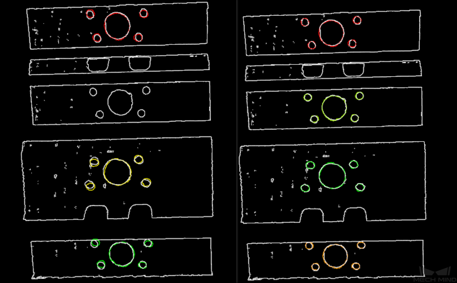
Figure 3. Comparison of outputs with small and large sampling intervals
Symmetry Settings ☆
When a part of the workpiece to be recognized is symmetrical, you will need to adjust the symmetry settings in order to escape a local optima of the matching result. An axis of the reference frame with the geometric center as its origin will be specified as the rotation axis, and the point cloud model will rotate around the specified axis according to the symmetry angle step and therefore the optimal matching result can be obtained.
- Symmetry Axis
- Default setting: ROTATE_BY_ZOptions: ROTATE_BY_X, ROTATE_BY_Y, ROTATE_BY_ZInstruction: This parameter specifies the axis of the reference frame with the geometric center as its origin, and the point cloud model will rotate around the specified axis.
- Angle Step
- Default setting: 360°Instruction: This parameter specifies the angle of rotational symmetry.Example: If an object looks the same before and after rotating 60° around an axis, its angle of rotational symmetry is 60°.
- Min Rotation Angle
- Default setting: -180°Instruction: This parameter adjusts the minimum rotation angle.
- Max Rotation Angle
- Default setting: 180°Instruction: This parameter adjusts the maximum rotation angle.
- Example
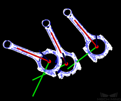
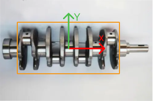
As shown in the figure below, the main part of the crankshaft, i.e., the part in the frame, has 180° rotational symmetry along the Y-axis.
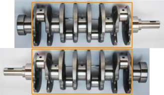
If you do not adjust the symmetry settings, there can be mismatches since the shapes of parts of the point cloud model and the crankshaft are similar, as shown below.
Only the middle part of the point cloud model and the crankshaft match with each other. However, if the point cloud model rotates 180°, it will match with the entire crankshaft, and the corresponding matching confidence will be higher.
After ROTATE_BY_Y (the Y-axis of the reference frame with the geometric center as its origin) is set as the Symmetry Axis, and the Angle Step is set to 180°, the point cloud model and the crankshaft match with each other correctly, as shown below.
Pose Filtering Settings ☆
- Filter Candidate Poses by Specified Axis Angles
- Default setting: UnselectedDescription: The pose with a significant angle difference between the constraint axis and the reference direction (larger than the angle difference upper threshold) will not be considered as candidate poses. It is usually used to filter out poses corresponding to mirror matching results. Once this option is selected, you will need to configure the Constraint Axis, Reference Direction, and Angle Difference Upper Threshold.
Model Weight in Validation ☆
- File of Model Fragments with Heigh Weight ☆
- Description: This .ply file contains the part of the point cloud model that needs to have a higher weight. The weight value is set by Weight of Each Point ☆ below.
For the reason of setting the weight, please see Weight in Point Cloud Matching below.
- Weight of Each Point ☆
- Default setting:
2.0Description: This parameter is to set the weight value for the parts with salient features in the point cloud model. The initial weight of all points is 1. After applying the weight, the points in the target part of the point cloud model will have a weight of this parameter. - Search Radius When Set Weight ☆
- Default setting:
0.003,0Description: This parameter is used to set the search radius when applying the weight. The weight setting is an operation performed on the original point cloud model. The point cloud model will be down-sampled before being used in the matching process, resulting in the shifting or loss of some points that need to be weighted. When setting the weight of the points near a missing point, the search radius needs to be set by this parameter.
Validation Settings
- Confidence Threshold
- Default setting:
0.500Minimum:0Description: The confidence threshold decides the standard by which each match between an object point cloud and its matched point cloud model is considered valid. Matches with confidences higher than the threshold are valid and those lower are not. The confidence of a match is a measure of the spatial closeness between the object point cloud points and its matched model’s point cloud points. Therefore, a lower threshold means more matches are valid for output and the output is less accurate, and a higher one means less valid matches but higher accuracy of the output.Limitation: Please note mismatches may still occur given a higher threshold, especially when the object’s different parts are of the same shape.Instruction:The Confidence Threshold needs to be tuned during testing for the optimal effect, its minimum is 0, but its maximum
maxshould be calculated as follows:Suppose the value of Weight of Each Point ☆ is
w. For the reason of setting the weight, please see Weight in Point Cloud Matching below.The ratio of weighted points to all the points in a point cloud model is
r, that is:r= point count of File of Model Fragments with Heigh Weight ☆ / point count of Model File<3d_fine_matching_model_file.max=w*r+ (1-r)Please set Confidence Threshold to a value between
0andmax.The point count of a point cloud is displayed on the lower left corner of the window that pops up by double clicking on the input/output ports in the graphical programming workspace. as shown below:
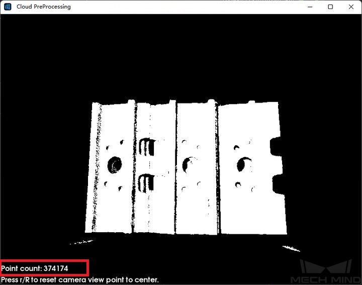
Figure 4. Point count of a point cloud
Example: Figure 4 below is an example showing two valid matches obtained under small and large confidence thresholds respectively. The confidence threshold of (a) is0.50and that of (b) is0.92. The match of (a) is more accurate than that of (b). Even though the comparison is not prominent, as 3D fine matching itself is a process of fine-tuning, the difference can still be observed, especially in the yellow boxes.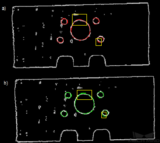
Figure 5. Comparison of matching results under different confidence thresholds with marks
- Search Radius
- Default setting:
0.01 mMinimum:0Description: It is the search radius when calculating the confidence. It is set by the sparseness of the object point cloud. If the point cloud is sparse, it needs to be set slightly larger. - Apply Angle Deviation in Validation ☆
- Default setting:
FalseOptions:True,FalseDescription: If set toTrue, during the validation, the angle difference of the normals of the corresponding points in a pair will be considered, and the number of output results will be reduced, but the output will be more accurate. - Multiply Corresponding Points Ratio in Scene ☆
- Default setting:
FalseOptions:True,FalseDescription: If set toTrue, the validation score of matching will be multiplied by the ratio of the number of the points with correspondence to the number of points in the entire point cloud. The validation score is printed in the log for debugging, and is printed only when the log level is set toDebug. It should be set toFalsefor obtaining the poses of multiple objects in a point cloud. Figure 6 is an example of validation scores printed in the log when debugging.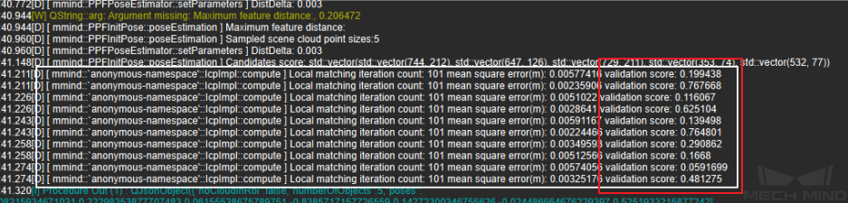
Figure 6. Validation scores in the log
Output Settings
- Maximum Number of Detected Poses in Each Point Cloud
- Default setting:
1Description: The larger the value, the more matching pairs will be output.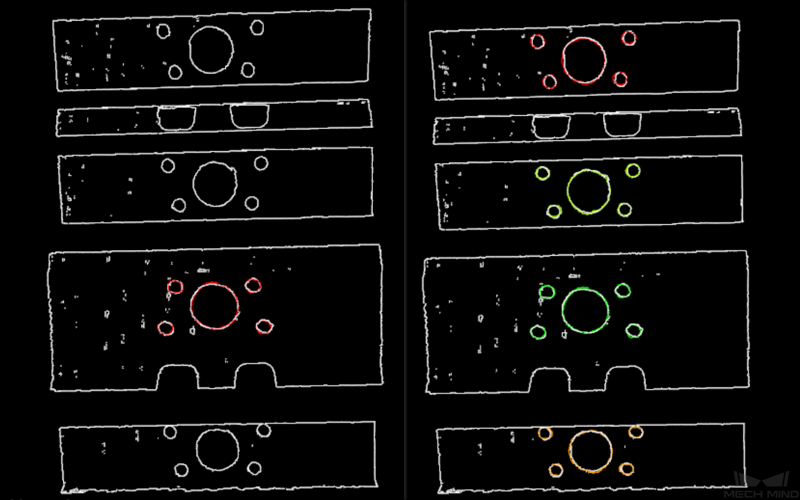
Figure 7. Comparison of single and multiple output results
Results Visualization
- Show Sampled Model Cloud ☆
- Default setting:
FalseOptions:True,FalseDescription: If set toTrue, the sampled point cloud model will be displayed in the output result. Please set by actual needs. - Show Sampled Scene Cloud ☆
- Default setting:
FalseOptions:True,FalseDescription: If set toTrue, the sampled object point cloud will be displayed in the output result. Please set by actual needs. - Show Validation Point Correspondences ☆
- Default setting:
FalseOptions:True,FalseDescription: If set toTrue, the correspondence between the model and the object point clouds will be displayed in the output result. Please set by actual needs. - Show Matching Results
- Default setting:
FalseOptions:True,FalseDescription: Display the output model and object point clouds when set toTrue.
Weight in Point Cloud Matching
Of an object, some parts have salient features, such as the corners, the holes, etc., and those parts should be paid special attention to by the matching algorithm to make the matching easier. Therefore, weights should be applied to the points of those parts in the point cloud so that the algorithm gives importance to those parts. In particular, weight should be applied when matching without weight does not work well.
Normally, among the points in a point cloud in Mech-Vision, a point is either not weighted or weighted by a fixed multiplier.
Yet please note that, after applying weight, mismatches may still occur especially when the object’s different parts are of the same shape or have similar features.
Parameters involved in weighting:
Weight of Each Point ☆
File of Model Fragments with Heigh Weight ☆
Model File<3d_fine_matching_model_file>