YASKAWA Example Program
This section introduces the example program provided with Mech-Center and the operations required to perform an actual pick-and-place task.
The example program mm_sample.JBI can be found in Mech-Center/mech_interface/yaskawa. It contains two parts: the first part obtains vision results from Mech-Vision; the second part obtains planned path from Mech-Viz.
Check the section corresponding to your own application setup:
Before running the program, please make sure that:
You have loaded the Standard Interface program onto the robot and can establish communcation with Mech-Center.
You have completed the extrinsic parameter calibration with the calibration program or by manually adding calibration points.
Mech-Vision and Mech-Viz projects are created and set to autoload.
The Project list in is synced by clicking on
 , and the order of Mech-Vision projects have been adjusted according to actual needs.
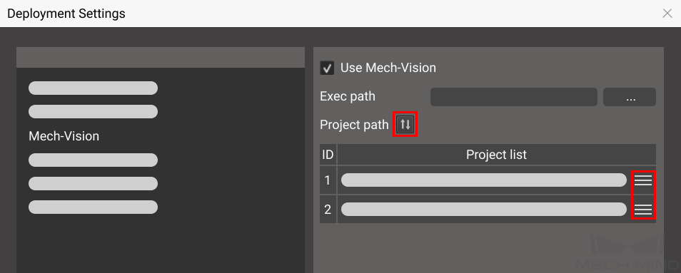
The TCP has been correctly specified.
The robot speed is set to a low value, so that the operator can notice any unexpected behavior before accidents occur.
Obtain Vision Results from Mech-Vision
35 36 37 38 39 40 41 42 43 44 45 46 47 48 49 50 51 52 53 54 55 56 57 58 59 60 61 62 63 64 65 66 67 68 69 70 71 72 73 74 75 76 77 78 79 80 81 82 83 84 85 86 87 88 89 90 91 92 93 | '*****************************
'FUNCTION:simple pick and place
'with Mech-Vision
'mechmind, 2022-5-27
'*****************************
'clear I50 to I69
CLEAR I050 20
'Initialize p variables
CNVRT PX070 PX070 RF TL#(1)
CNVRT PX071 PX071 RF TL#(1)
CNVRT PX072 PX072 RF TL#(1)
CNVRT PX073 PX073 RF TL#(1)
SUB P070 P070
SUB P071 P071
SUB P072 P072
SUB P073 P073
'move robot home position
MOVJ C00000 VJ=1.00
'camera capture position
MOVJ C00001 VJ=1.00 PL=0
'set ip address of IPC
CALL JOB:MM_INIT_SOCKET ARGF"192.168.170.22;50000;1"
TIMER T=0.20
'set vision recipe
'MM_SET_MODEL("1,1")
'Run vision project
CALL JOB:MM_START_VIS ARGF"1;2;2"
TIMER T=1.00
'get result from Vis
CALL JOB:MM_GET_VISDATA ARGF"1;50;51;52"
TIMER T=0.20
PAUSE IF I052<>1100
'set the first pos to P071;
'set lables to I61;
'set speed to I62;
CALL JOB:MM_GET_POSE ARGF"1;71;61;62"
PAUSE IF I061<>1
'set -200mm to Z
SETE P070 (3) -200000
MULMAT P072 P071 P070
'set -300mm to Z
SETE P070 (3) -300000
MULMAT P073 P071 P070
'way point
MOVJ C00002 VJ=1.00
MOVL P072 V=80.0 PL=0
MOVL P071 V=80.0 PL=0
'enable girpper
DOUT OT#(1) ON
MOVL P073 V=80.0 PL=0
MOVJ C00003 VJ=1.00
'drop point
MOVJ C00004 VJ=1.00 PL=0
'release gripper
DOUT OT#(1) OFF
'way point
MOVJ C00005 VJ=1.00
'move robot home position
MOVJ C00006 VJ=1.00
|
Program Logic
Move the robot to HOME position.
Move the robot to the image capturing pose.
Initialize communication with MM_INIT_SOCKET.
If parameter recipes are used in the Mech-Vision project, the recipe to be used is set with MM_SET_MODEL.
Run the Mech-Vision project with MM_START_VIS.
Wait for 1 second. Under Eye-In-Hand, this TIMER instruction is required to make sure the robot stays still until image acquisition is completed. Under Eye-To-Hand, this TIMER instruction can be replaced with MOVJ or MOVL.
Obtain the vision results from Mech-Vision.
Check if the returned status code indicates any error. If an error code is returned, the program is paused.
Move the robot to the picking pose and perform picking.
Move the robot to a waypoint between the picking pose and placing pose.
Move the robot to the set placing pose and perform placing.
Return the robot to HOME position.
The following parts should be modified according to your actual needs.
Define the TCP
Change TL#(1) to the tool number to which the actual TCP is saved.
Note
Do not use TOOL 0 as it is used for calibration in MM_AUTO_CALIB.
Teach the Image Capturing Pose
Record the image capturing pose in C00001 in line 54.
Teach the Waypoint(s)
Waypoints are intermediate poses between the picking pose and placing pose. They are used to ensure that the robot doesn’t collide with the surrounding when moving between the picking and placing poses.
Record the waypoints to C00002 in line 79 and C00005 in line 91. You can add more waypoints if needed.
Teach the Placing Pose
Record the placing pose in C00004 in line 87.
Define Z-Offset from Picking/Placing Pose
Z-offset distances relative to the tool frame from the picking/placing pose are used to ensure collision doesn’t occur when the robot is approching or departing the picking/placing pose.
The MULMAT function is used to calculate and store the pose representing the offset from the picking pose in a new variable.
Adjust the following commands according to your actual needs.
SETE P070 (3) -200000 in line 73: the Z-offset when approching the picking pose is set to 200 mm. Robot will move to P072, which is 200 mm above the picking pose.
SETE P070 (3) -300000 in line 75: the Z-offset when departing the picking pose is set to 300 mm. Robot will move to P073, which is 300 mm above the picking pose.
Add Object Grasping and Releasing Logics
Modify DOUT OT#(1) ON in line 83 to the actual logic for controlling the tool action when picking the object.
Modify DOUT OT#(1) OFF in line 89 to the actual logic for controlling the tool action when placing the object.
Define HOME position
Teach HOME position to C00000 in line 52.
Obtain Planned Path from Mech-Viz
94 95 96 97 98 99 100 101 102 103 104 105 106 107 108 109 110 111 112 113 114 115 116 117 118 119 120 121 122 123 124 125 126 127 128 129 130 131 132 133 134 135 136 137 138 139 140 141 142 143 144 145 146 147 148 149 150 151 152 153 154 155 156 | '*****************************
'FUNCTION:simple pick and place
'with Mech-Viz
'mechmind, 2022-5-27
'*****************************
'clear I50 to I69
CLEAR I050 20
'Initialize p variables
CNVRT PX071 PX071 RF TL#(1)
CNVRT PX072 PX072 RF TL#(1)
CNVRT PX073 PX073 RF TL#(1)
SUB P071 P071
SUB P072 P072
SUB P073 P073
'move robot home position
MOVJ C00007 VJ=1.00
'camera capture position
MOVJ C00008 VJ=1.00 PL=0
'set ip address of IPC
CALL JOB:MM_INIT_SOCKET ARGF"192.168.170.22;50000;1"
TIMER T=0.20
'set vision recipe
CALL JOB:MM_SET_MODEL ARGF"1;1"
TIMER T=0.20
'Run Viz project
CALL JOB:MM_START_VIZ ARGF"1"
TIMER T=0.20
CALL JOB:MM_SET_BRANCH ARGF"1;1"
'get result from Viz
TIMER T=1.00
CALL JOB:MM_GET_VIZDATA ARGF"2;50;51;52;53"
TIMER T=0.20
PAUSE IF I053<>2100
'set the first pos to P071;
'set lables to I61;
'set speed to I62;
CALL JOB:MM_GET_POSE ARGF"1;71;61;62"
PAUSE IF I061<>1
'set the second pos to P072;
'set lables to I63;
'set speed to I64;
CALL JOB:MM_GET_POSE ARGF"2;72;63;64"
PAUSE IF I063<>1
'set the third pos to P073;
'set lables to I65;
'set speed to I66;
CALL JOB:MM_GET_POSE ARGF"3;73;65;66"
PAUSE IF I065<>1
'way point
MOVJ C00009 VJ=1.00
MOVL P071 V=80.0 PL=0
MOVL P072 V=80.0 PL=0
'enable girpper
DOUT OT#(1) ON
MOVL P073 V=80.0 PL=0
'way point
MOVJ C00010 VJ=1.00
'drop point
MOVJ C00011 VJ=1.00 PL=0
'release gripper
DOUT OT#(1) OFF
'move robot home position
MOVJ C00012 VJ=1.00
|
Program Logic
Move the robot to HOME position.
Move the robot to the image capturing pose.
Initialize communication with MM_INIT_SOCKET.
If parameter recipes are used in the Mech-Vision project, the recipe to be used is set with MM_SET_MODEL.
Run the Mech-Viz project with MM_START_VIZ.
Obtain the planned path from Mech-Viz.
Check if the returned status code indicates any error. If an error code is returned, the program is halted.
Store obtained target points in the planned path to P071, P072, and P073.
Move the robot along the planned path and perform picking.
Move the robot to a waypoint between the picking pose and placing pose.
Move the robot to the set placing pose and perform placing.
Return the robot to HOME position.
The following parts should be modified according to your actual needs.
Define the TCP
Change TL#(1) to the tool number to which the actual TCP is saved.
Note
Do not use TOOL 0 as it is used for calibration in MM_AUTO_CALIB.
Teach the Image Capturing Pose
Record the image capturing pose in C00001 in line 111.
Teach the Waypoint(s)
Waypoints are intermediate poses between the picking pose and placing pose. They are used to ensure that the robot doesn’t collide with the surrounding when moving between the picking and placing poses.
Record the waypoint to C00009 in line 143. You can add more waypoints if needed.
Teach the Placing Pose
Record the placing pose in C00011 in line 152.
Add Object Grasping and Releasing Logics
Modify DOUT OT#(1) ON in line 147 to the actual logic for controlling the tool action when picking the object.
Modify DOUT OT#(1) OFF in line 154 to the actual logic for controlling the tool action when placing the object.
Define HOME position
Teach HOME position to C00007 in line 109.