YASKAWA Setup Instructions
This section introduces the process of loading the Standard Interface program onto a YASKAWA robot.
The process consists of 4 steps:
Please have a flash drive ready at hand.
Note
A USB 2.0 flash drive is recommended. Otherwise, the robot controller may not recognize the flash drive.
Check Controller and Software Compatibility
Robot: 6-axis YASKAWA robot
Controller: YRC1000 (excluding YRC1000 micro) and DX200
Option function requirements: must have the MotoPlus and Ethernet functions enabled.
Note
The following instructions are based on YRC1000 controller. Details may differ for DX200 controller.
Setup the Network Connection
Hardware Connection
Plug the Ethernet cable into:
An Ethernet port on the IPC
LAN2 (CN106) port on YRC1000 controller; CN104 port on DX200 controller
Note
LAN1 port on YRC1000 and CN105 port on DX200 are for connecting the teach pendant only.
If LAN2 port is occupied, please use LAN3 (CN107) instead.
IP Configuration
To allow communication between the IPC and the robot controller, both must have an IP address in the same subnet. This means that the first three numbers of the IP addresses should be the same. For example, 192.168.100.1 and 192.168.100.2 are in the same subnet.
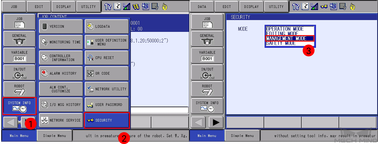
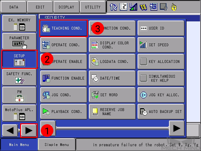
Press down MAIN MENU when powering on the controller to enter the maintenance mode.
Select .
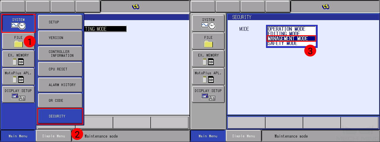
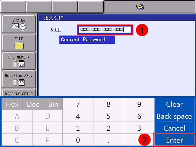
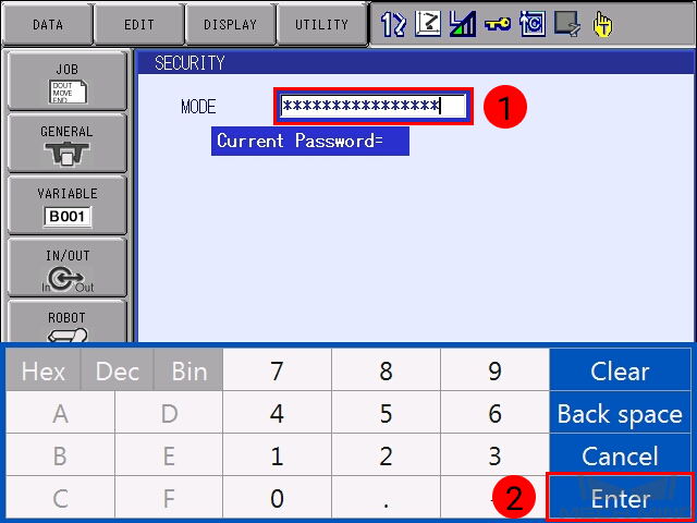
Enter the password (the default password is sixteen 9 ‘s), and then press on Enter.
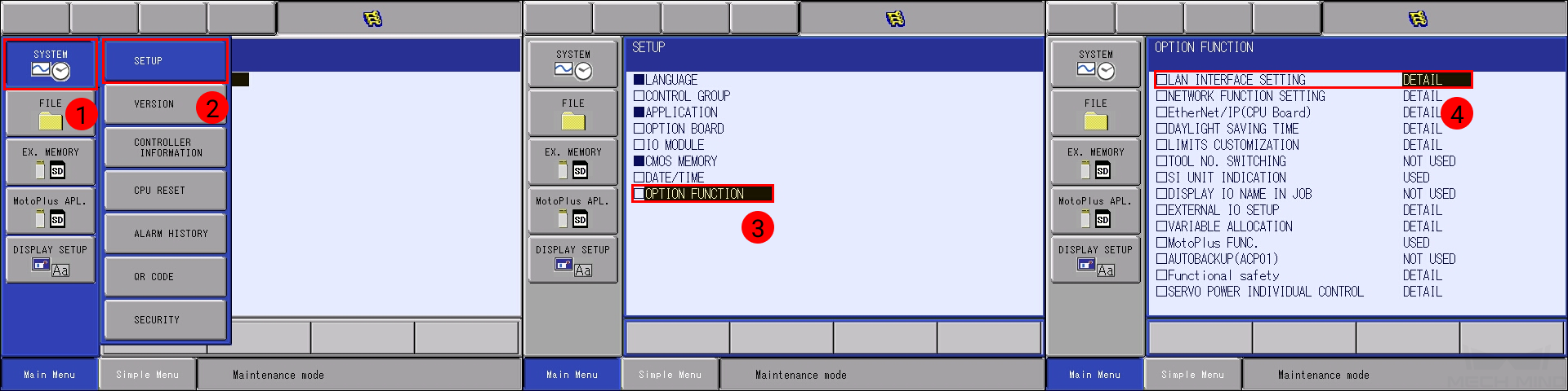
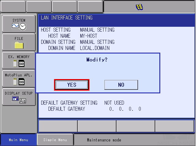
Select .
In IP ADDRESS SETTING(LAN2), select MANUAL SETTING, and then set the IP ADDRESS to one in the same subnet as the IPC, and the SUBNET MASK to 255.255.255.0.
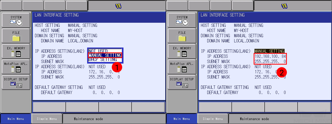
Press the ENTER key, and then press on YES in the pop-up message.
Load the Program Files
Prepare the Files
The program files are stored in the installation directory of Mech-Center. The default directory is C:/Mech-Mind/Mech-Center.
Navigate to xxx/Mech-Center/mech_interface/yaskawa, and copy the following files to your flash drive。
JBI folder
yrc1000.out if you are using a YRC1000 controller
dx200.out if you are using a DX200 controller
Note
Copy the file to the root directory of the flash drive. Do not put it in another folder or rename it.
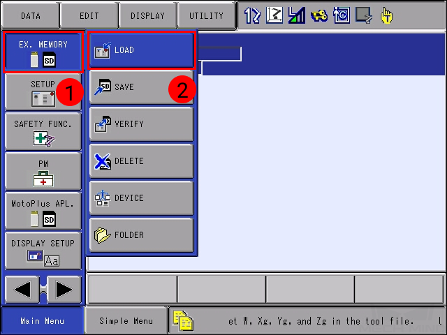
Load the MotoPlus Application File to the Robot
Insert the flash drive into the USB port on the back of the teach pendant.
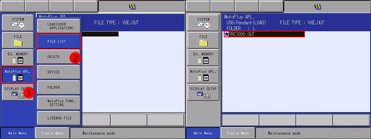
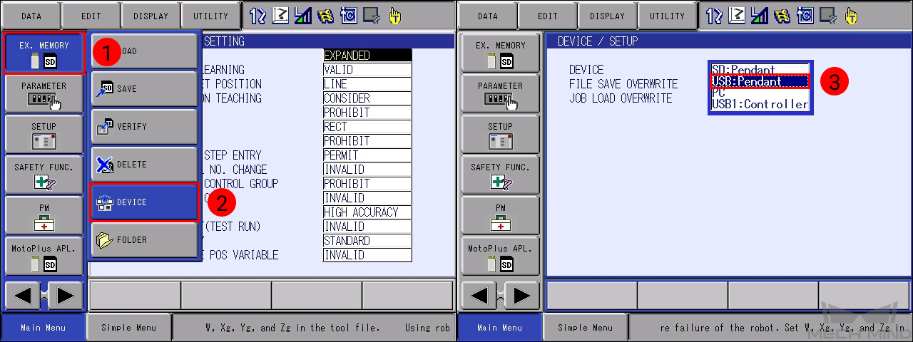
Under maintenance mode, select .
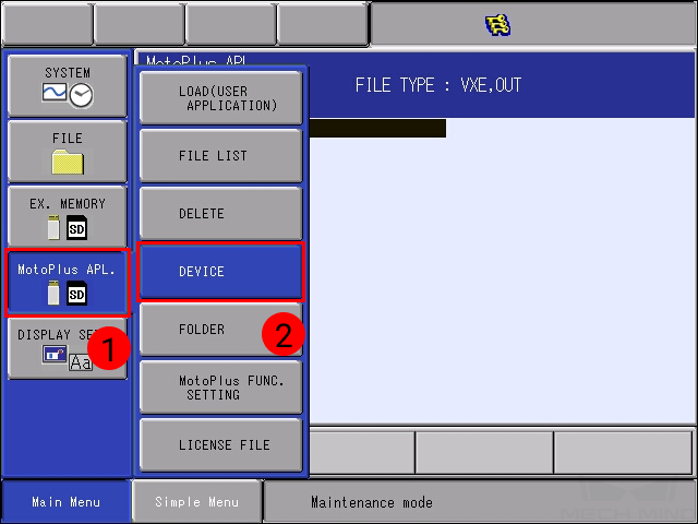
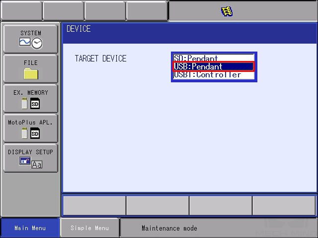
Select USB:Pendant for TARGET DEVICE.
Select .
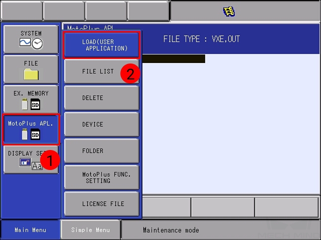
Select YRC1000.OUT (DX200.OUT for DX200 controller), and press ENTER. Select YES in the pop-up message to start loading the program.
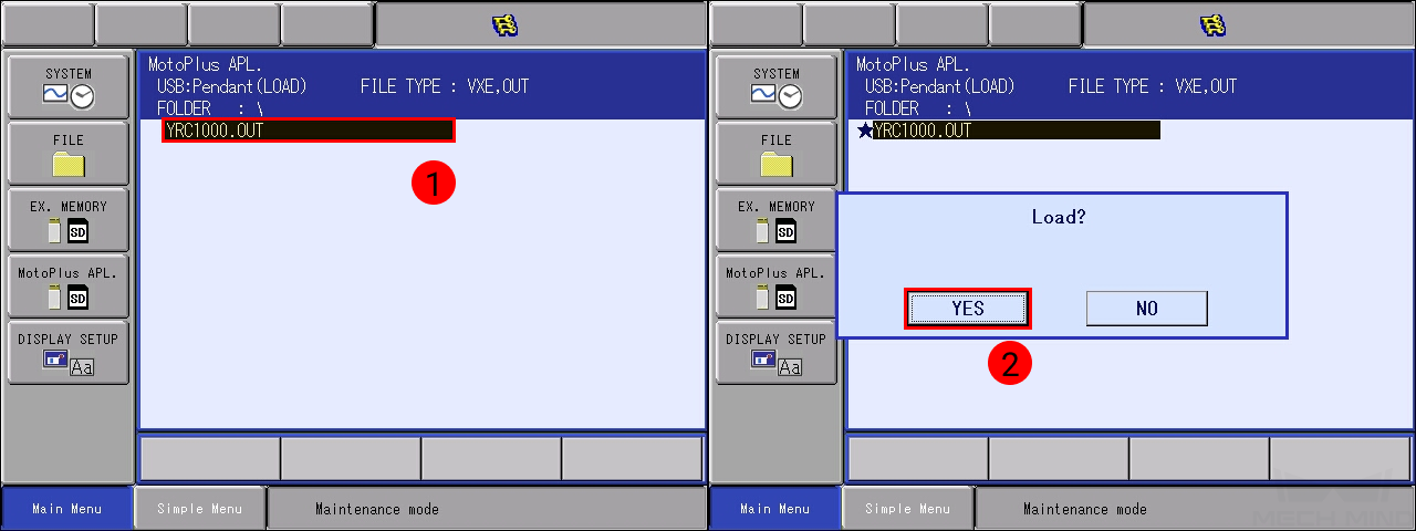
After loading completes, go to , and you should see YRC1000.OUT (DX200.OUT) displayed.
Load the Job Files to the Robot
Restart the controller without pressing the MAIN MENU key, and select .
Enter the password (the default password is sixteen 9 ‘s), and then press on Enter.
Press on the right arrow button, and select
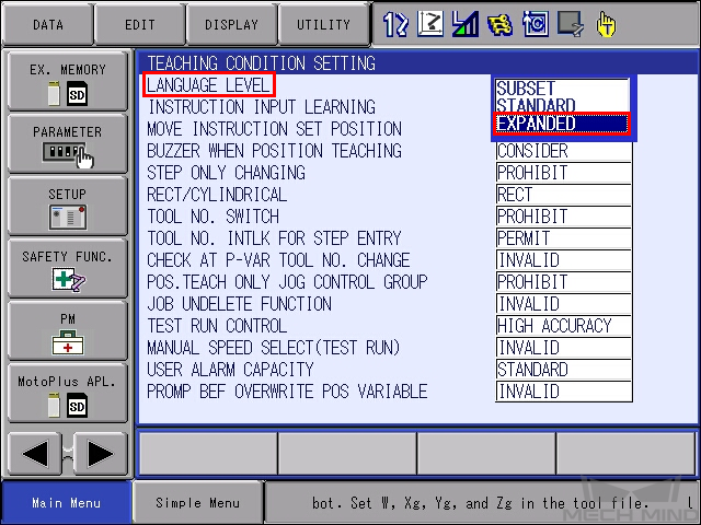
Set LANGUAGE LEVEL to EXPANDED.
Select , and then select USB:Pendant for DEVICE.
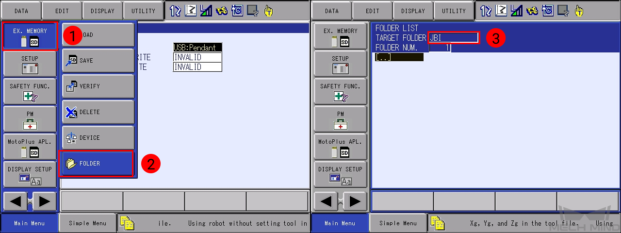
Select , and then select JBI from the list.
Note
Make sure you are IN the JBI folder (JBI is displayed after TARGET FOLDER).
Select .
Select , and then press ENTER. Select YES in the pop-up message to start loading the programs.
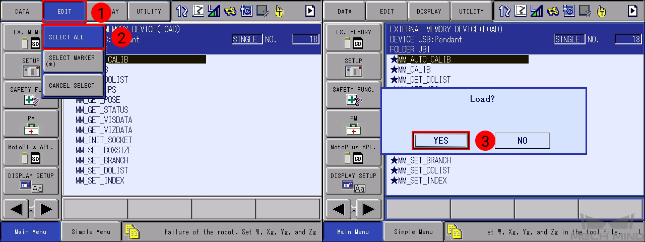
After loading completes, go to , and you should see all the job files displayed.
Test Robot Connection
Configure Mech-Interface in Mech-Center
Open Mech-Center and click on Deployment Settings.
Go to Mech-Interface, check Use Mech-Interface and select Standard Interface.
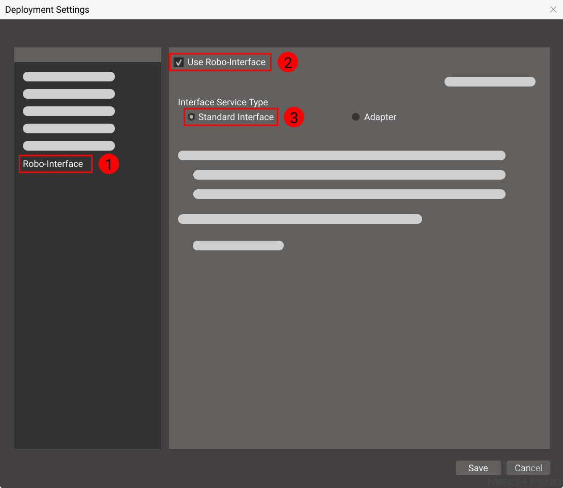
Set the following fields:
Interface Option: Set to TCP Server and ASCII.
Listed robot: Select the robot model you are using.
Host Address: The default port number is 50000. If you need to change the port number, make sure to change it later on in the robot program as well.
Click on Save.
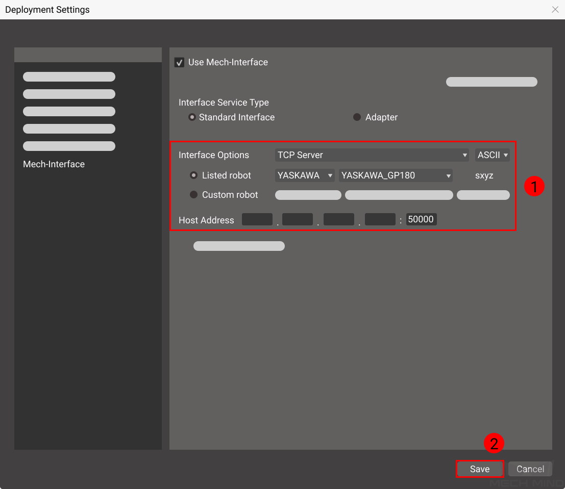
Click on Start Interface in the Toolbar.
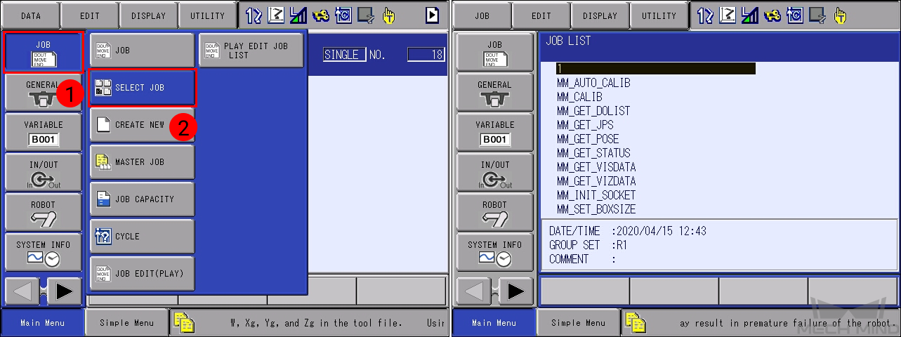
Modify and Run Robot Program
Select .
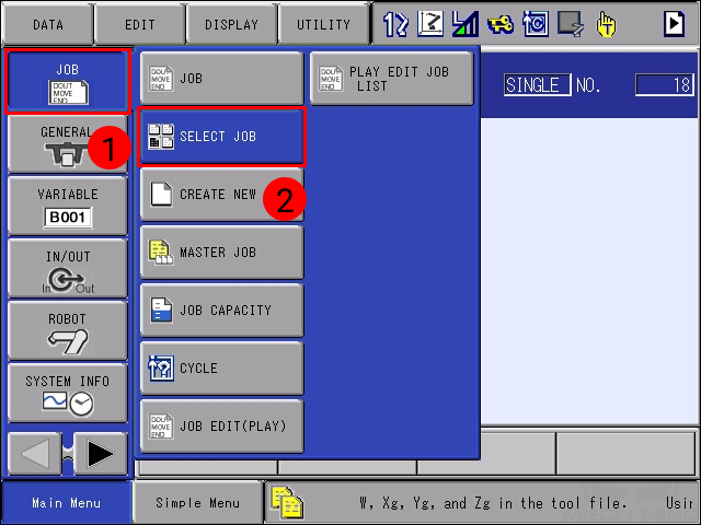
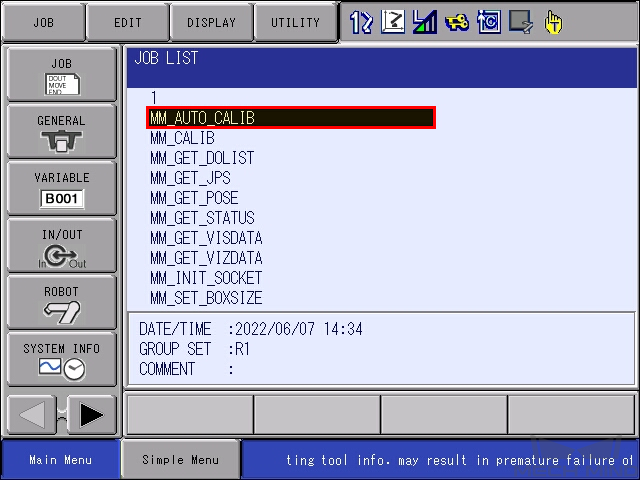
Select MM_AUTO_CALIB in the JOB LIST, and then press the SELECT key.
Change the IP address and port number in line 0001 to the actual ones of the IPC:
Move the cursor to the instruction side of line 0001, and press SELECT. a text box will show on the bottom.
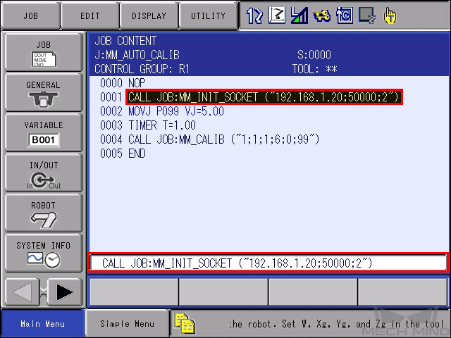
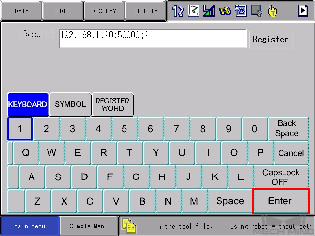
In the text box, move the cursor to the IP address and port number, and press ENTER.
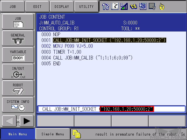
Change the IP address and port number, and then press on Enter.
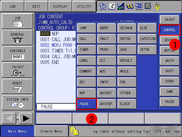
Insert a PAUSE command after line 0001: make sure the cursor is on line 0001, and press INFORM LIST. Select in the pop-up menu, and press INSERT and then ENTER.
Turn the mode switch to TEACH mode, press the SERVO ON READY key, and then hold down the enable switch on the back while moving the cursor back to line 0000.
Press the INTERLOCK key and TEST START key at the same time; the job will start running and should be paused after line 0001.
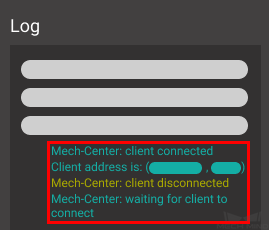
The robot can be successfully connected if Mech-Center’s Log panel displays the following messages:
Mech-Center: client connected
A message showing the client address
Mech-Center: client disconnected
Mech-Center: waiting for client to connect
Note
Delete PAUSE after testing the connection to avoid pausing the robot by mistake during calibration.