PROFINET - Siemens SIMATIC S7 PLC
This section provides information on setting up communication between a Siemens SIMATIC S7 PLC and Mech-Mind Software Suite via PROFINET.
Overview
Hardware and Software Requirements
Hardware
Siemens SIMATIC S7 PLC:
S7-300 (with PROFINET interface or CP 343-1 integrated to function as a PROFINET IO controller)
S7-400 (with PROFINET interface or CP 443-1 integrated to function as a PROFINET IO controller)
S7-1200
S7-1500
AC 220 V to DC 24 V power adapter
HMS IXXAT INpact 40 interface card installed on the IPC in Mech-Mind Vision System
Switch
Ethernet cables
Software
Siemens TIA Portal V15.1
Mech-Mind Software Suite: Mech-Center 1.5.1 or above, Mech-Vision 1.5.0 or above, and Mech-Viz 1.5.0 or above.
VCI V4 (driver software for HMS IXXAT INpact 40 interface card)
Mech-Mind GSD file:
File name: GSDML-V2.35-Mech-Mind Robotics Technologies Ltd-MechMind-PIR-20220315.xml (The version number and date in the file name may differ.)
File location: Mech-Mind/Mech-Center/mech_interface/PROFINET (the installation directory of Mech-Center)
Note
Copy this file to the computer with Siemens TIA Portal installed.
Example programs:
File name: PLC sample.zip
File location: Mech-Mind/Mech-Center/mech_interface/documents/CN/Siemens PROFINET编程指南 (the installation directory of Mech-Center)
Note
Copy this ZIP file to the computer with Siemens TIA Portal installed, and unzip it to get the following files: Camera_IO.scl, ObtainPose.scl, PLCTags.xlsx.
Note
Connect the Mech-Mind Vision System IPC, computer with Siemens TIA Portal installed, and PLC to the same router.
Configure IPC and Initiate Communication
Check PCI-e Card and Driver Software
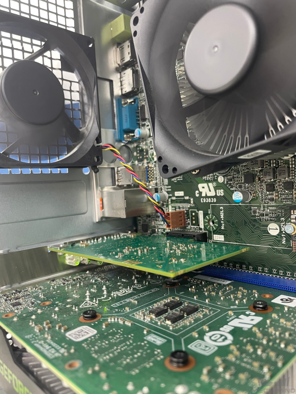
Check the PCI-e slot on the IPC and make sure the HMS IXXAT INpact 40 interface card is installed.
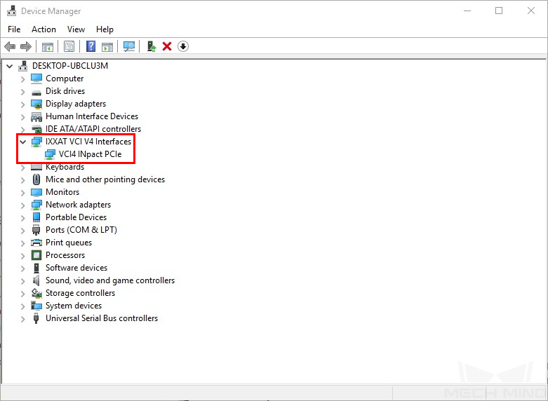
Make sure the driver software is installed on the IPC: in Device Manager, find VCI4 INpact PCIe under IXXAT VCI V4 Interfaces.
Configure Mech-Interface in Mech-Center
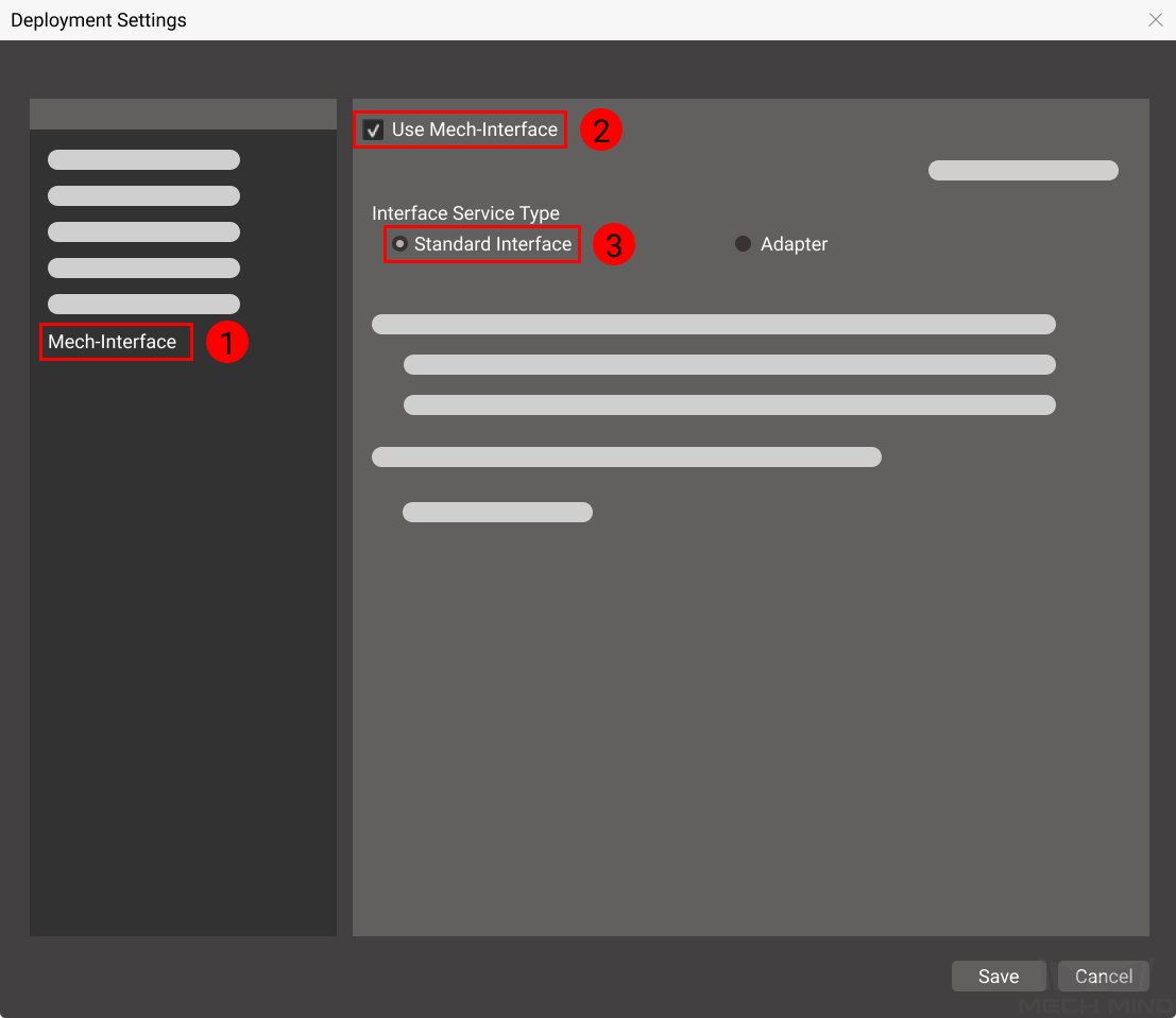
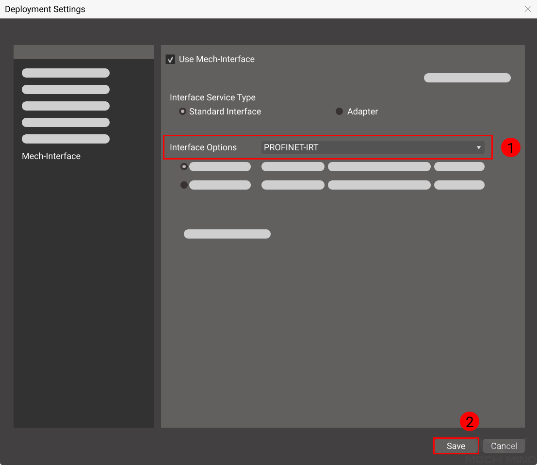
Open Mech-Center, and click on Deployment Settings.
Go to Mech-Interface, check Use Mech-Interface and select Standard Interface.
In Interface Options, select PROFINET-IRT, and then click on Save.
Click on Start Interface in the Toolbar.
Install GSD file and Configure Communication
Create PLC Project and Set IP Address
Hint
If needed, click on Save project to save the changes to the project.
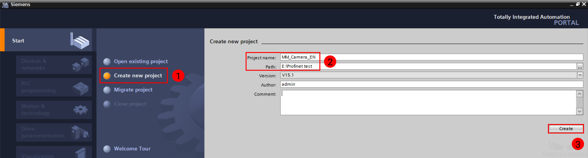
Open TIA Portal and click on Create new project.
Put in Project name and Path, and then click on Create. Click on Open the project view in the pop-up page.
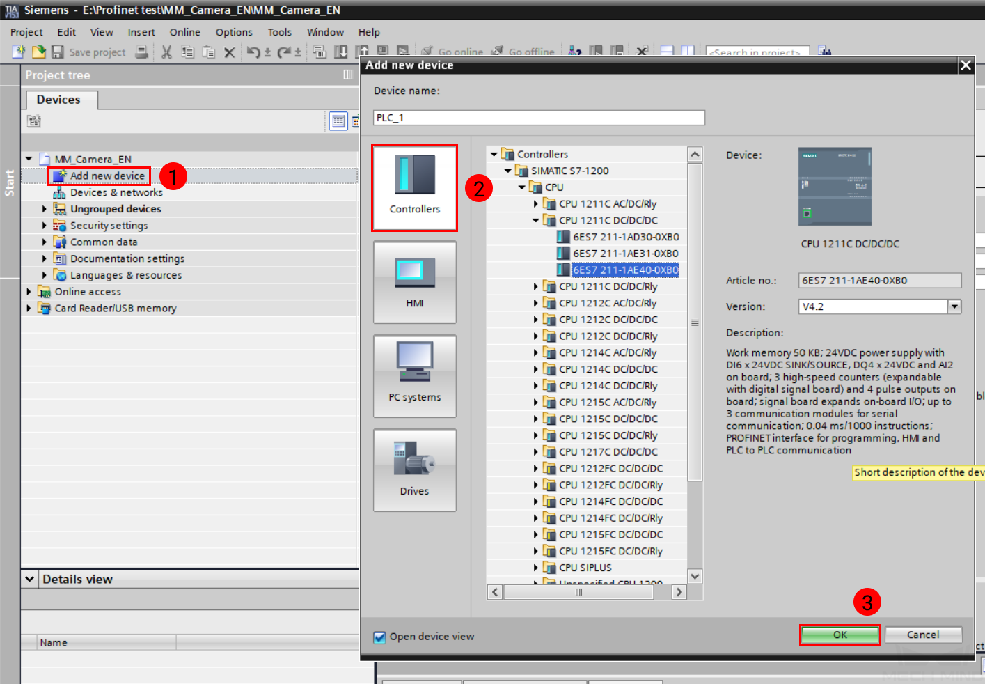
In the Project tree panel, double-click on Add new device. In the new window, click on Controller, and find the CPU module you are using, and name it in Device name. Click on OK to confirm adding the device. Here, the device is named PLC_1.
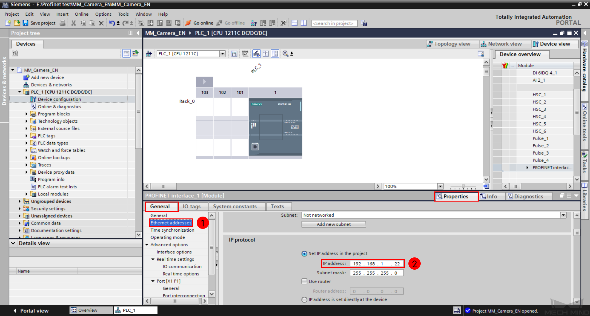
In Device view, click on
 is PLC_1. If you don’t see the following interface, first click on Device configuration under PLC_1 in the Project tree panel, and then click on Device view tab on the right.
Down in the tab, click on Ethernet address to set the IP address of the PLC.
Install GSD File and Configure Network
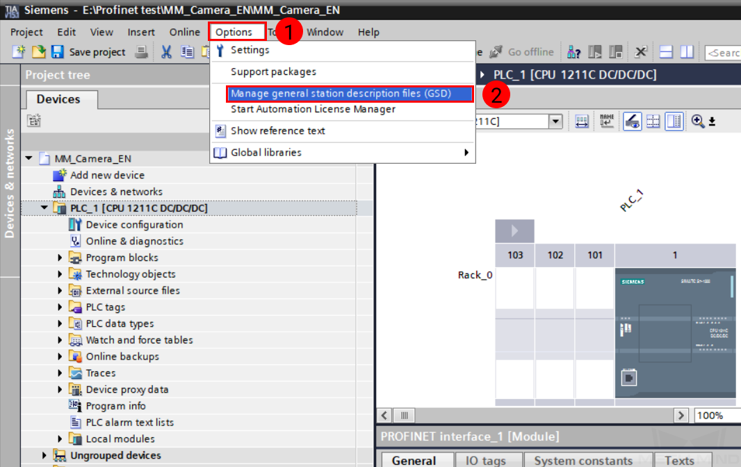
In the menu bar, select .
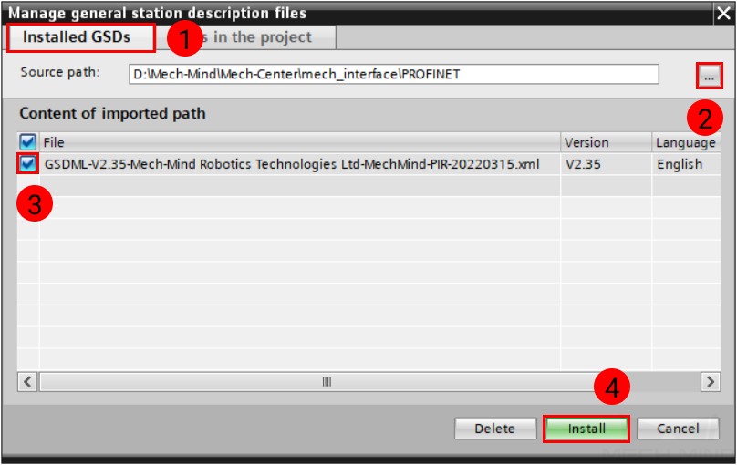
In the pop-up window under Installed GSDs tab, click on … to the right of Source path. Locate the path where the Mech-Mind GSD file is stored. Check this file in Content of imported path, and then click on Install. Close the window after the installation completes.
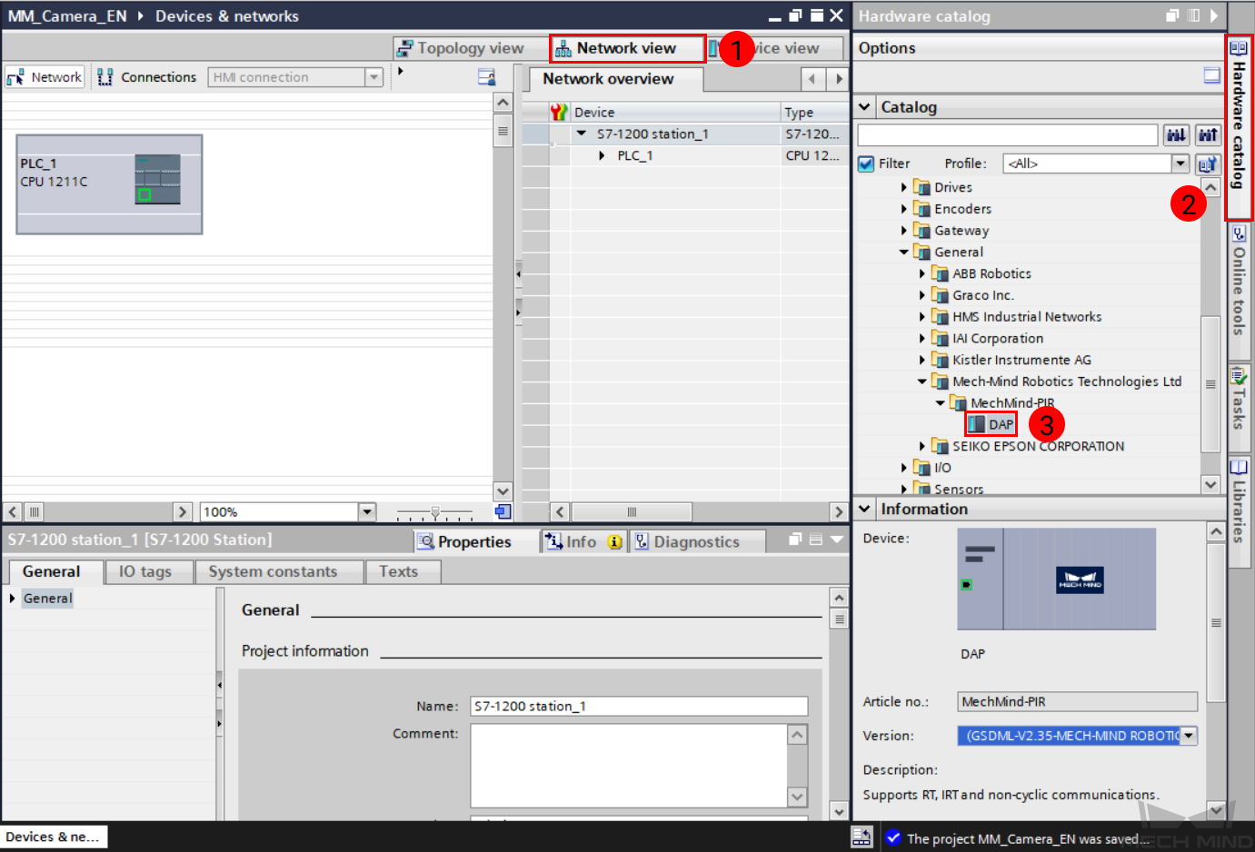
Return to Device configuration, and go to Network view tab. Click on Hardware catalog, and double-click on DAP under Other field devices/PROFINET IO/General/Mech-Mind Robotics Technologies Ltd/MechMind-PIR to display mechmind-pir in Network view.
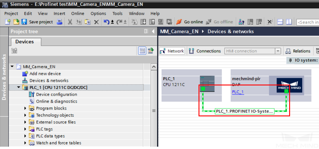
In Network view, click on
in PLC_1 and drag it to in mechmind-pir, and release the button when a black connection line appears.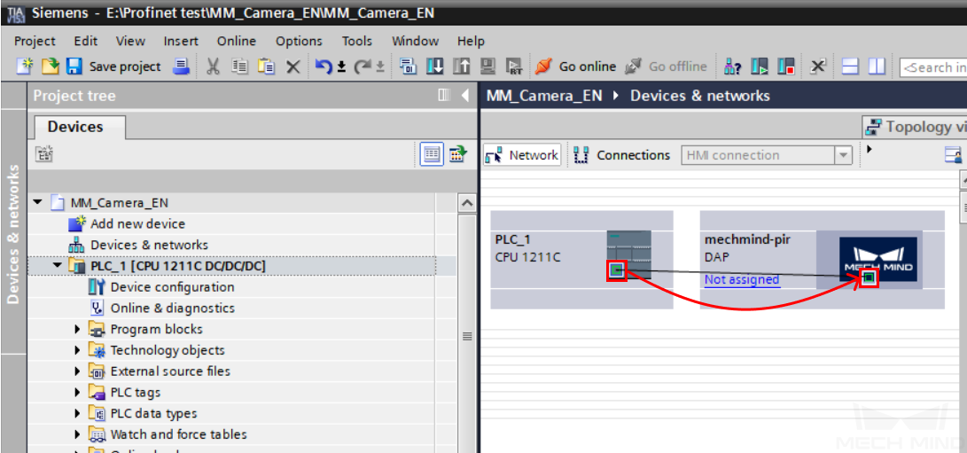
A successful connection should look like this:
Click on
in mechmind-pir, down in the tab, click on Ethernet address to set the IP address of the IPC. This IP address should be in the same subnet as that of the PLC. Make sure Generate PROFINET device name automatically is checked.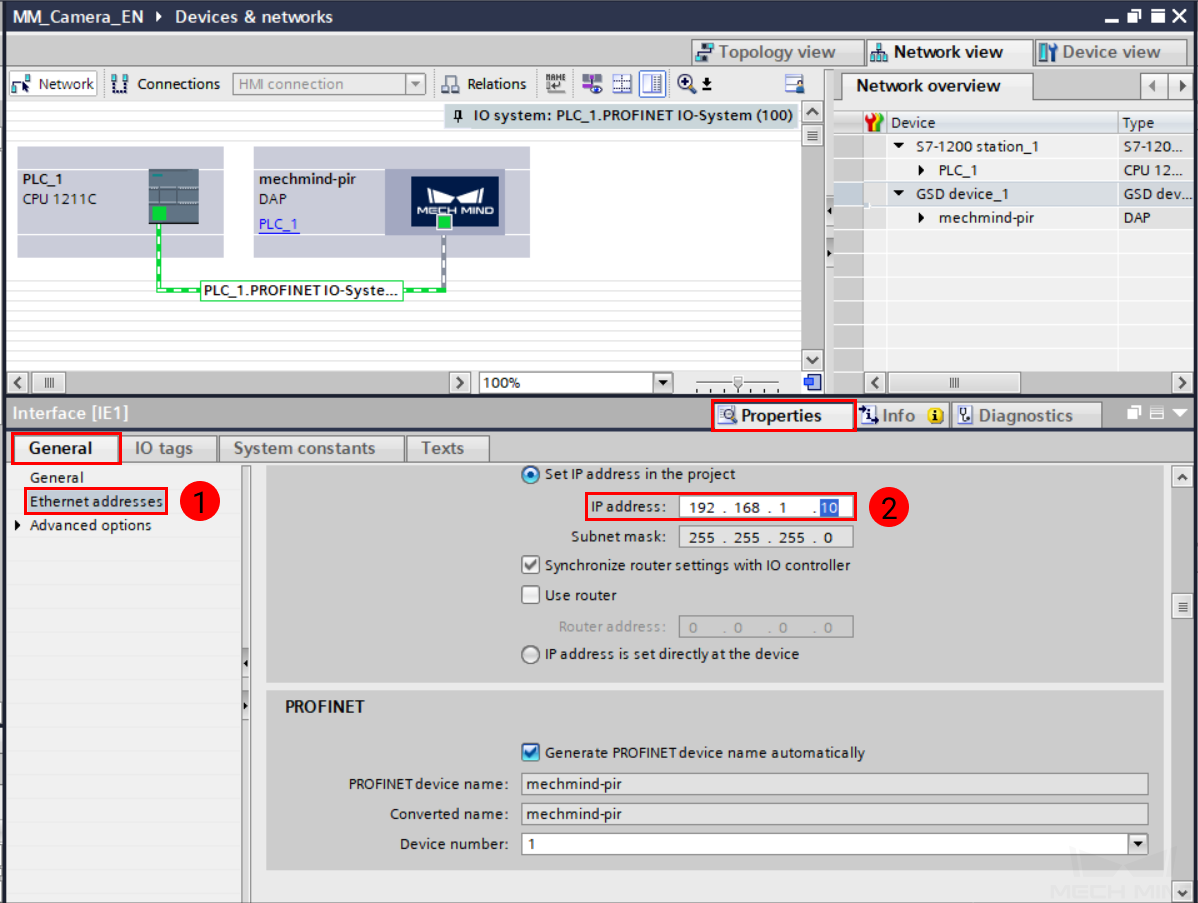
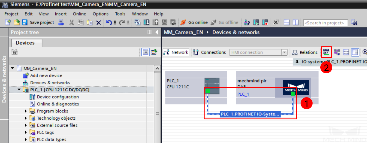
Click on the green connection line, and then click on
 .
.
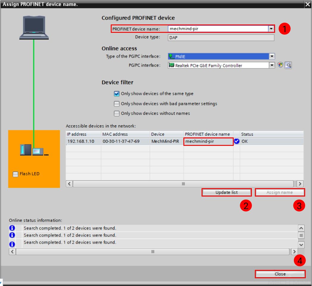
In the pop-up window, select mechmind-pir for PROFINET device name, and then click on Update list.
When the device appears in the list, check whether the PROFINET device name is mechmind-pir. If not, click on Assign name. Once Status is OK, click on Close to close the window.
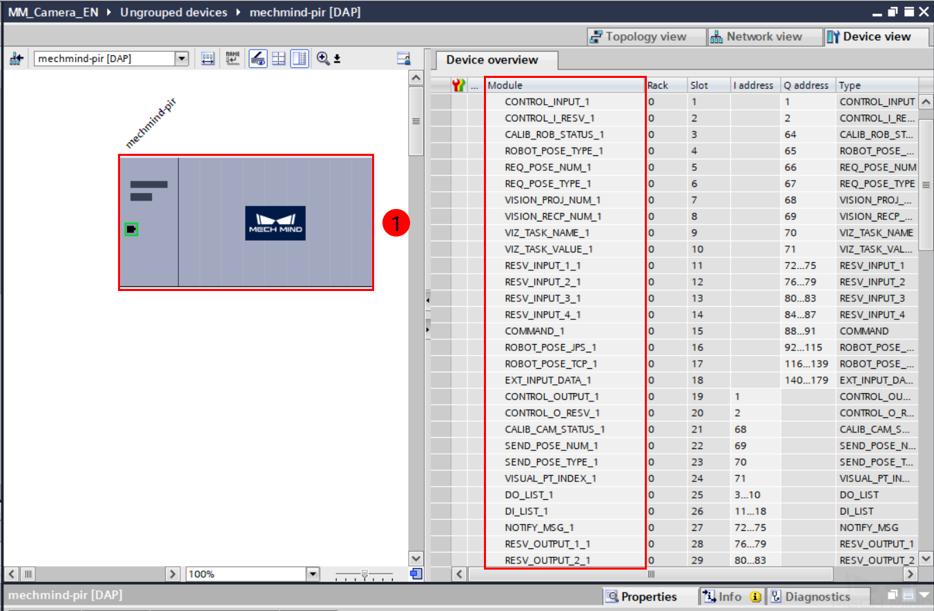
Double-click on mechmind-pir to enter Device view. You can see all the available modules listed.
Download Hardware Configuration to PLC
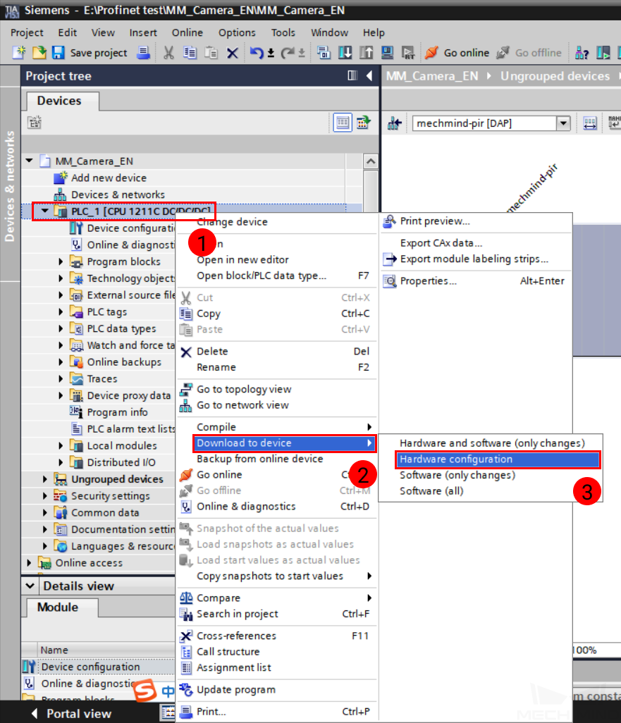
In Project tree panel, right-click on PLC_1, and select .
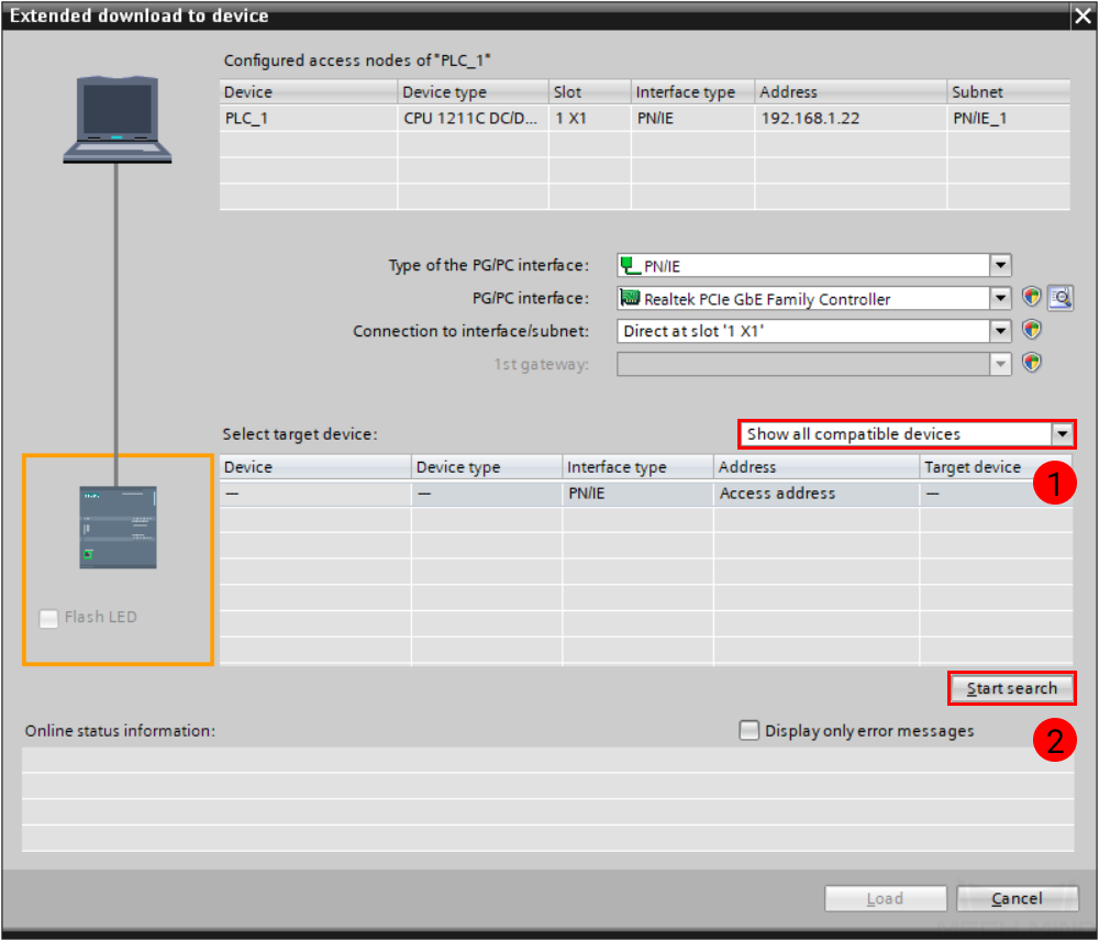
In the pop-up window, select Show all compatible devices for Select target device, and then click on Start search.
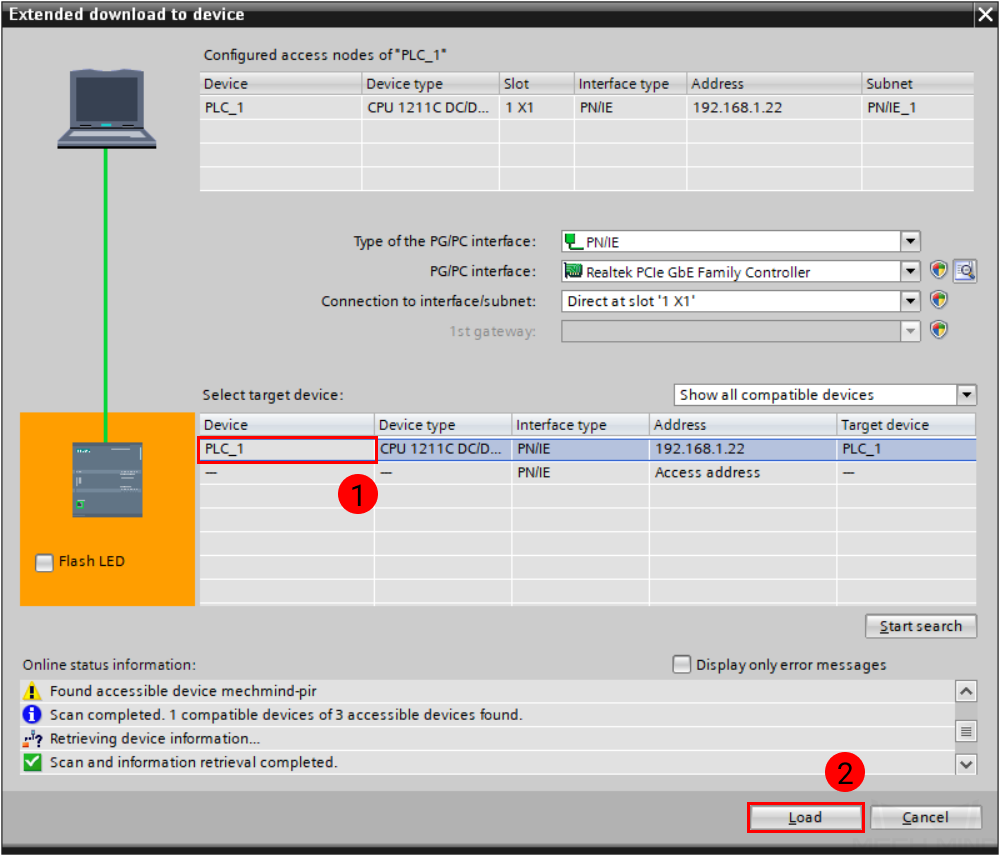
Select the corresponding device in the search result, and click on Load.
Check Communication
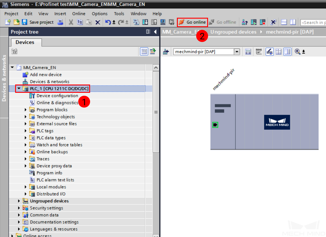
Return to the project, and click on PLC_1 in the Project tree panel. Then, click on Go online in the toolbar.
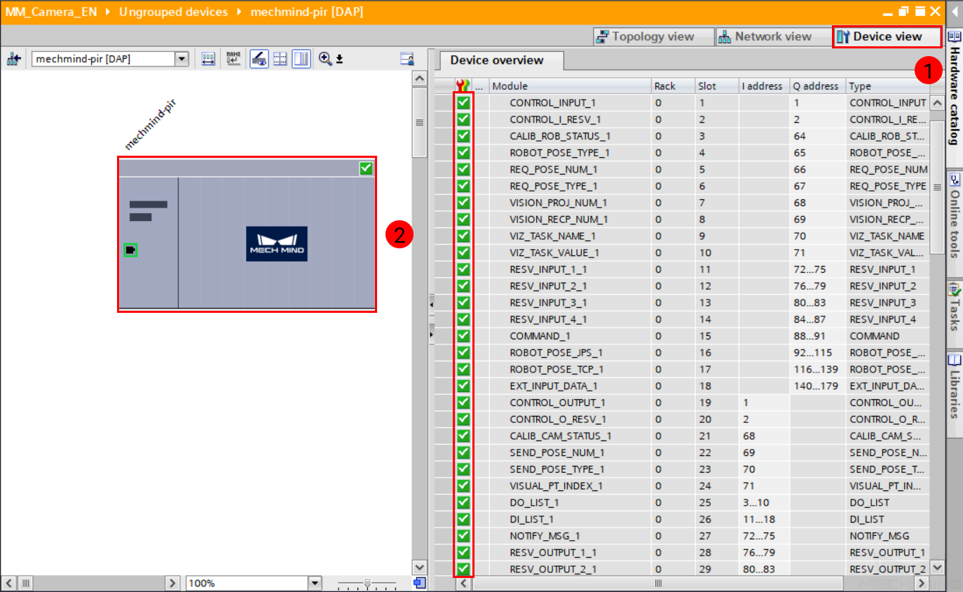
In the Project tree panel, click on Device configuration, and then click on Device view tab on the right. Select mechmind-pir. In Device overview, check marks with a green background in front of module names indicate normal connection.
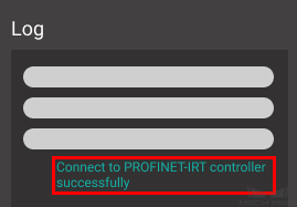
The PLC is successfully connected to Mech-Center if the following message is displayed in Mech-Center Log panel:
Connect to PROFINET-IRT controller successfully
Note
If you don’t see this log message, please check if:
The hardware are properly connected;
If Mech-Interface has been started by clicking on Start Interface in the Toolbar;
If the hardware configuration has been downloaded to the PLC.
Import Example Program and Download to PLC
Note
Before you add the example program to a project already in use, it is recommended to import it to a new project and test it first. In the following steps, the project created earlier is used to import and test the example program.
Import Example Program Files
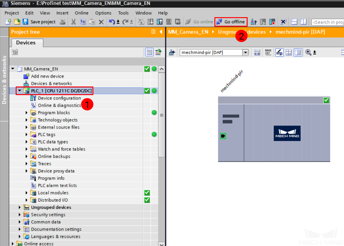
Select PLC_1 in the Program tree panel, and then click on Go offline in the toolbar.
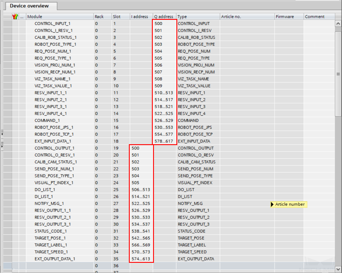
In Network view, double-click on mechmind-pir to enter Device view. Change the I addresses and Q addresses according to your actual needs. Here, 500 is used as the lowest module start address.
Note
For a module occupying multiple bytes, the addresses assigned must be continuous, and the module start address must be of an even number.
In Project tree panel, double-click on PLC tags under PLC_1, and then double-click on Show all tags to open the PLC tags window. Then, click on
 to import tags.
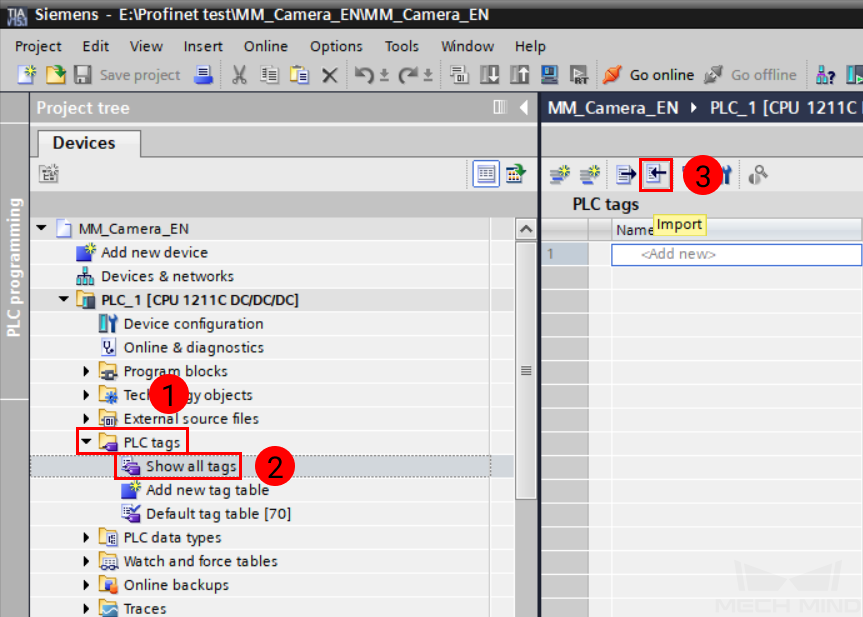
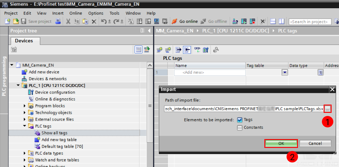
Click on … to the right of the input field, and locate the PLCTags.elsx file. Click on OK to import the PLC tags.
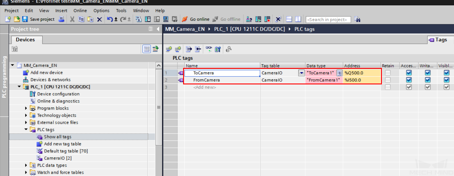
The following tags should be imported. Change the address of ToCamera and FromCamera to the same as those of CONTROL_INPUT_1 and CONTROL_OUTPUT_1 modules, respectively.
In the Project tree panel, double-click on External source files, and then double-click on Add new external file.
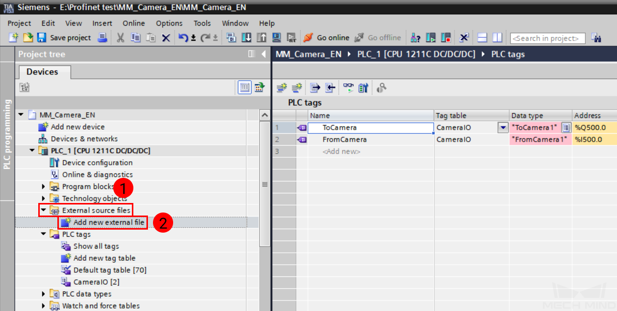
In the pop-up window, locate and select the Camera_IO.scl and ObtainPose.scl files. Click on Open to import these files.
Select the two imported external files and then right-click on these files. In the right-click menu, select Generate blocks from source.
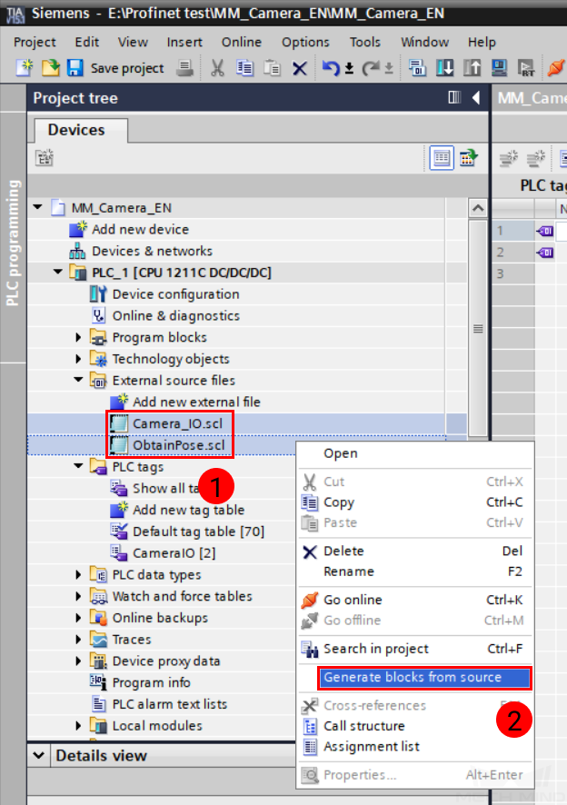
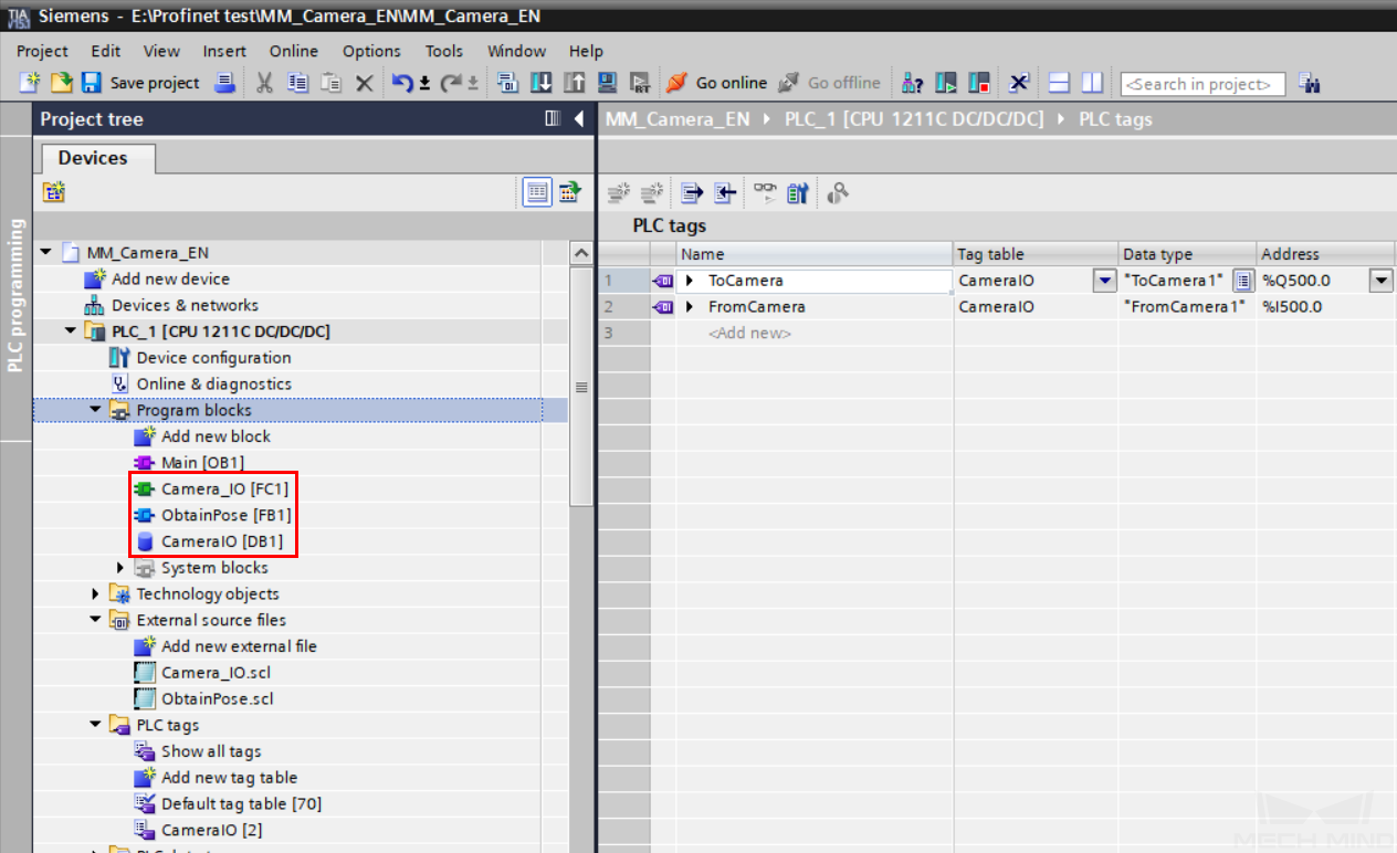
Three program blocks should be generated: Camera_IO FC, ObtainPose FB, and CameraIO DB.
Build Program and Download to PLC
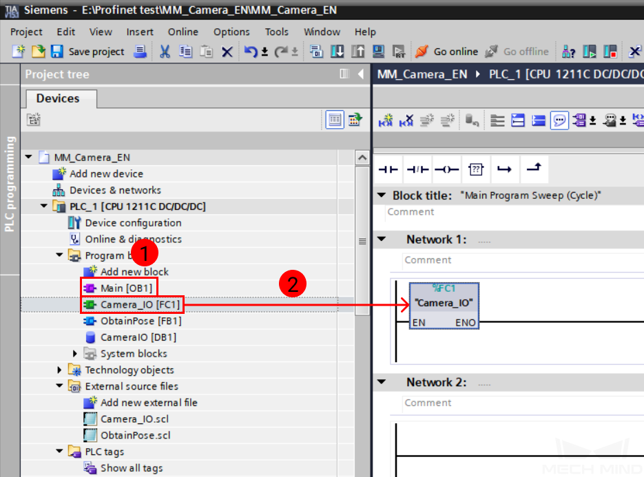
In the Program tree panel, double-click on the Main OB in Program blocks to open it. Then, select Camera_IO FC and drag it to Network 1.
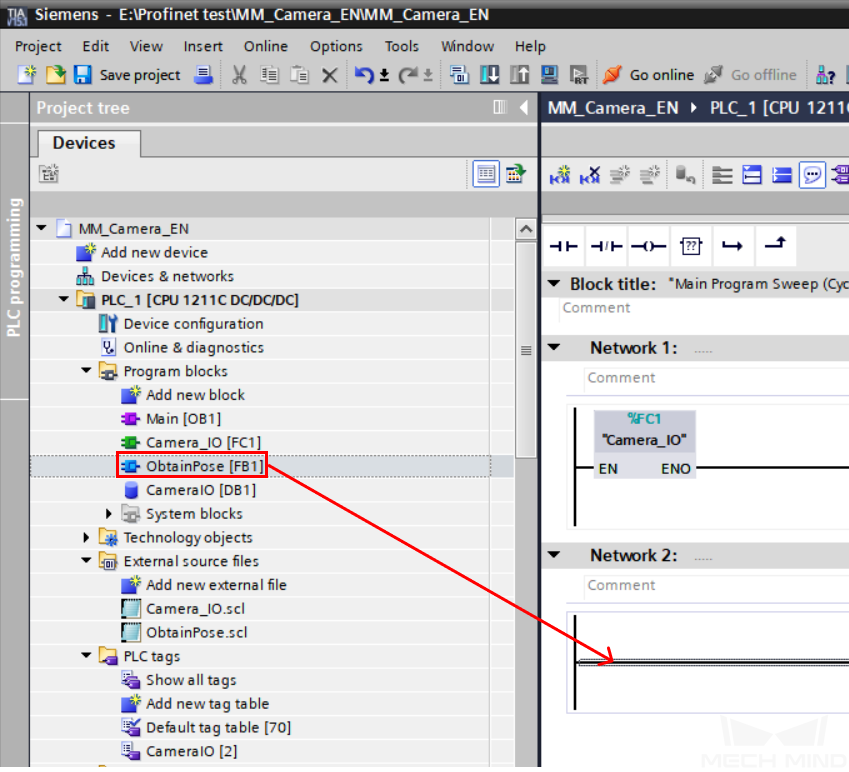
Select ObtainPose FB and drag it to Network 2. A window will pop-up when you release the mouse button.
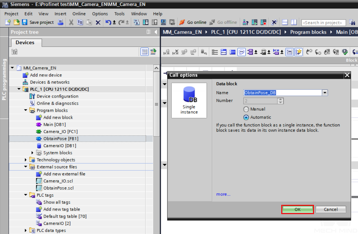
In the pop-up window, keep the default options and click on OK.
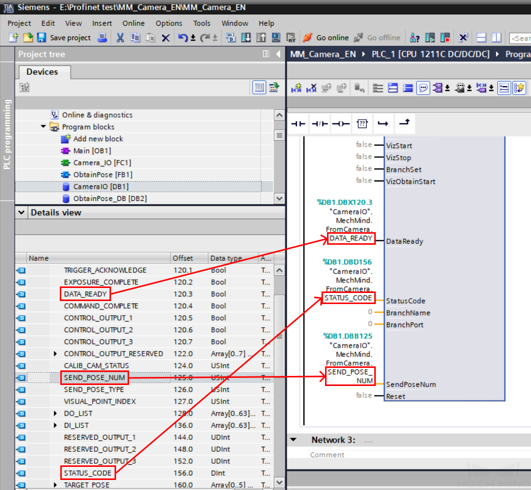
Click on CameraIO DB, and under the Details view, drag DATA_READY, SEND_POSE_NUM and STATUS_CODE to the input ports with the same names on the left side of ObtainPose FB.
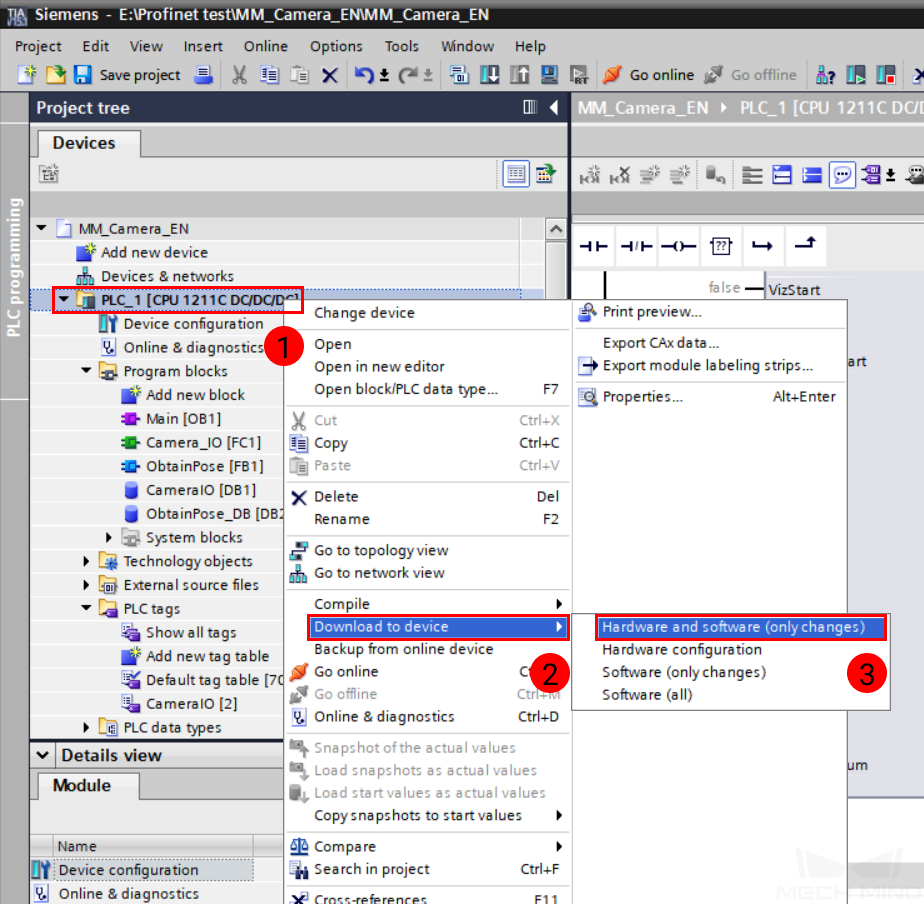
In the Program tree panel, right-click on PLC_1, and select . Refer to steps 2 and 3 in Download Hardware Configuration to PLC above and download the program to the PLC.
After downloading, select PLC_1 in the Program tree panel, and click on Go online.
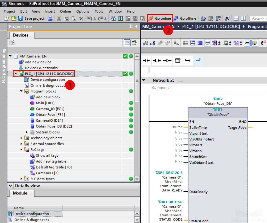
In the Program tree panel, double-click on and then click on
 . Double-click to expand . If the monitor value of HEARTBEAT keeps changing, then the I/Q addresses of modules in mechmind-pir have been successfully transferred to the CameraIO FB.
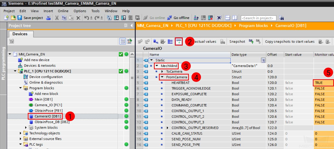
Test with Mech-Vision/Mech-Viz Project
This section introduces how to run the Mech-Vision/Mech-Viz project and obtain data from the project using the ObtainPose FB. For detailed information on the modules, please refer to PROFINET.
Prerequisites
Mech-Vision project(s):
Executable
Set to autoload
The Project list in is synced by clicking on
 , and the order of Mech-Vision projects have been adjusted according to actual needs.
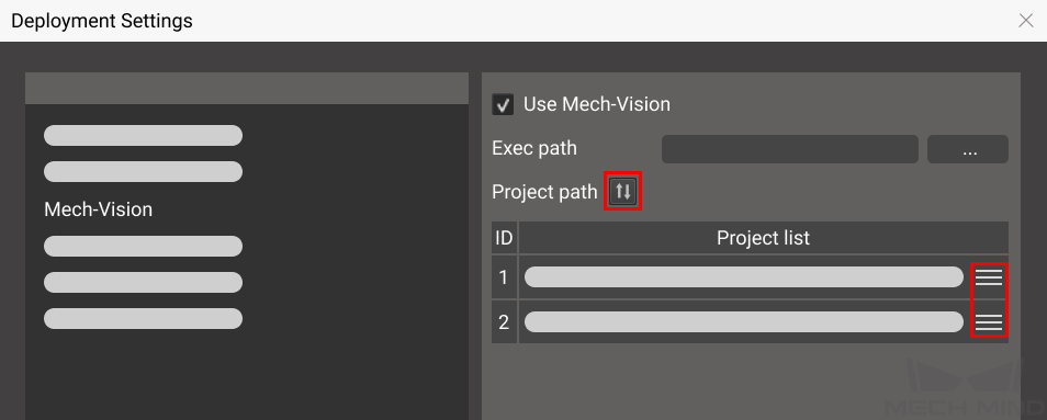
Mech-Viz project:
Executable
Set to autoload
Contains a branch_by_service_message Task that has been renamed to 1.
Run Mech-Vision Project and Obtain Vision Points
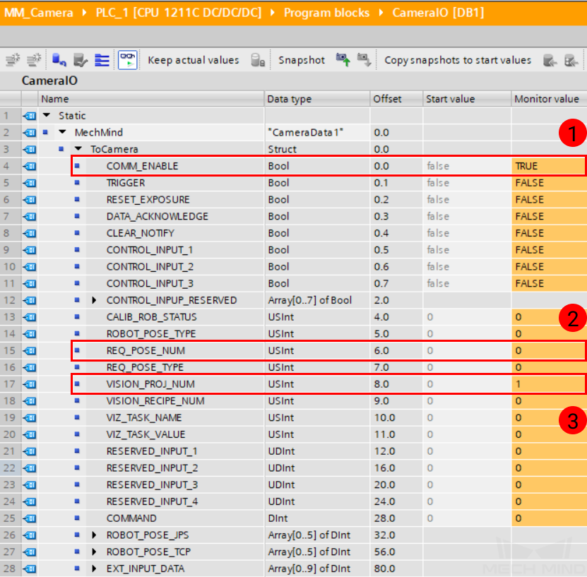
Enable communication: in the CameraIO DB, double-click on the monitor value of COMM_ENABLE in ToCamera. If a warning message pops up, click on Yes to confirm changing the monitor value.
Set Mech-Vision project ID: change the monitor value of VISION_PROJ_NUM to the ID of the Mech-Vision project you wish to run. For example, if the monitor value is changed to 1, then Mech-Vision project No. 1 in the Project list of Mech-Center will be started.
Set the number of vision points to be sent by Mech-Vision: change the monitor value of REQ_POSE_NUM. If the value is set to 0, the Mech-Vision project will send all the vision points.
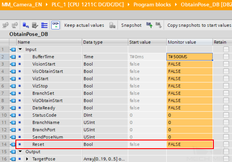
Set the hold time of signals sent to the IPC: double-click on ObtainPose_DB DB, and click on
. Under Input group, change the monitor value of BufferTime to 500MS.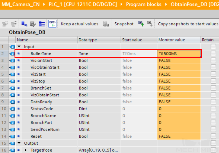
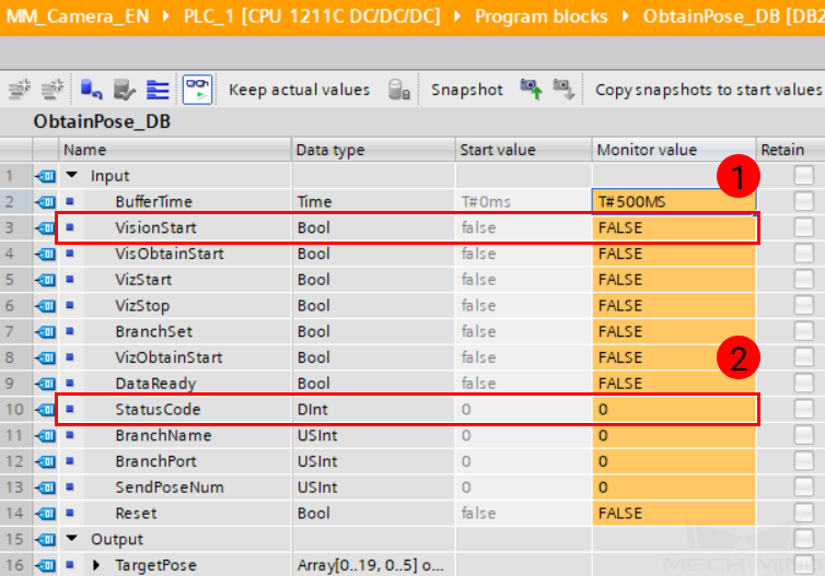
Start the Mech-Vision project: in the ObtainPose_DB DB, double-click on the monitor value of VisionStart to change it to TRUE. Then, reset the monitor value to FALSE.
Check returned status code: check the monitor value of StatusCode. 1102 represents that the Mech-Vision project was started successfully. For other values, please refer to Status Codes for the corresponding error.
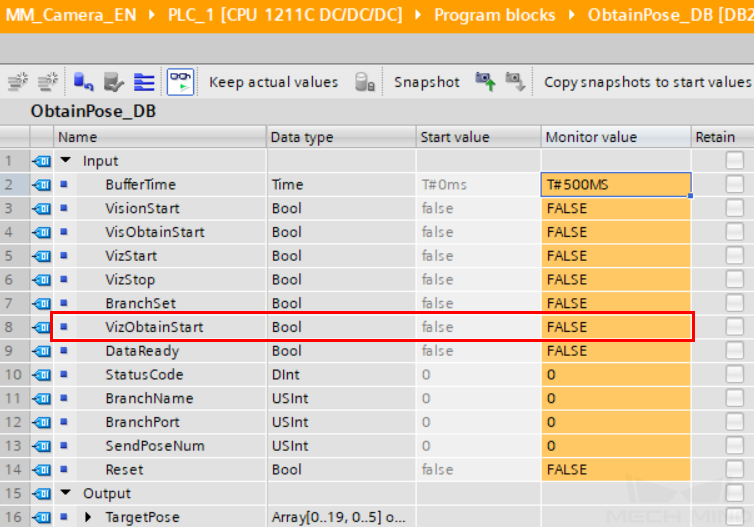
Obtain vision points from the Mech-Vision project: in the ObtainPose_DB DB, double-click on the monitor value of VisObtainStart to change it to TRUE. Then, reset the monitor value to FALSE.
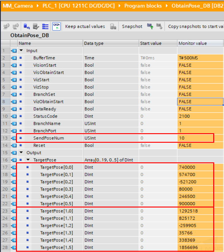
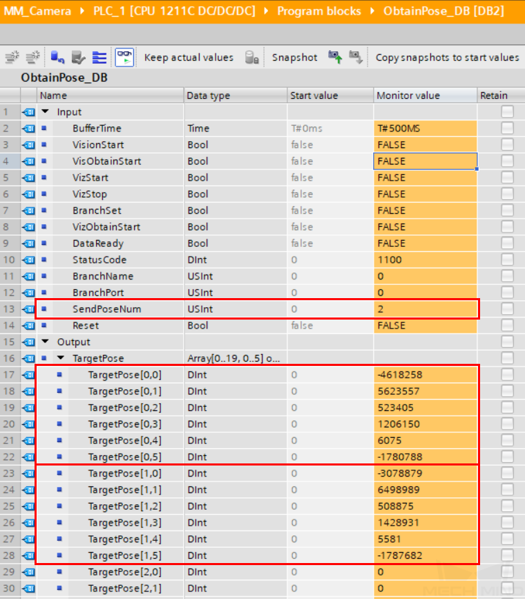
Check the received vision points: the monitor value of SendPoseNum shows how many vision points were received, and the vision points are stored in TargetPose. Divide the monitor values by 10000 to obtain the actual pose data.
Run Mech-Viz Project and Obtain Planned Path
Clear last obtained data: in the ObtainPose_DB DB, double-click on the monitor value of Reset to change it to TRUE. Then, reset the monitor value to FALSE.
Set the branch to take in the Mech-Viz project:
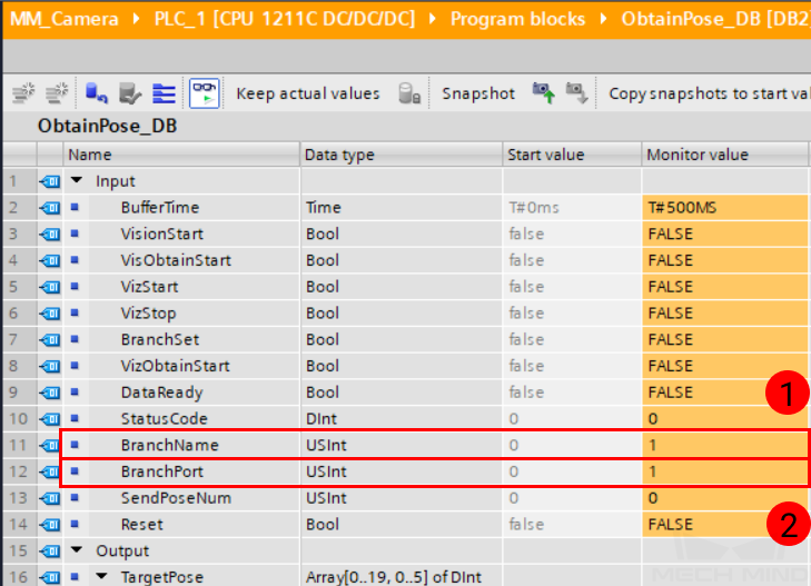
Set Task name: in the ObtainPose_DB DB, change the monitor value of BranchName to 1. This tells Mech-Viz that you are trying to select the out port for the Task named 1.
Select out port: change the monitor value of BranchPort to the out port you would like the Mech-Viz project to take in Task 1. For example, if you set the value of BranchPort to 1, the Mech-Viz project will proceed along out port 1 of Task 1.
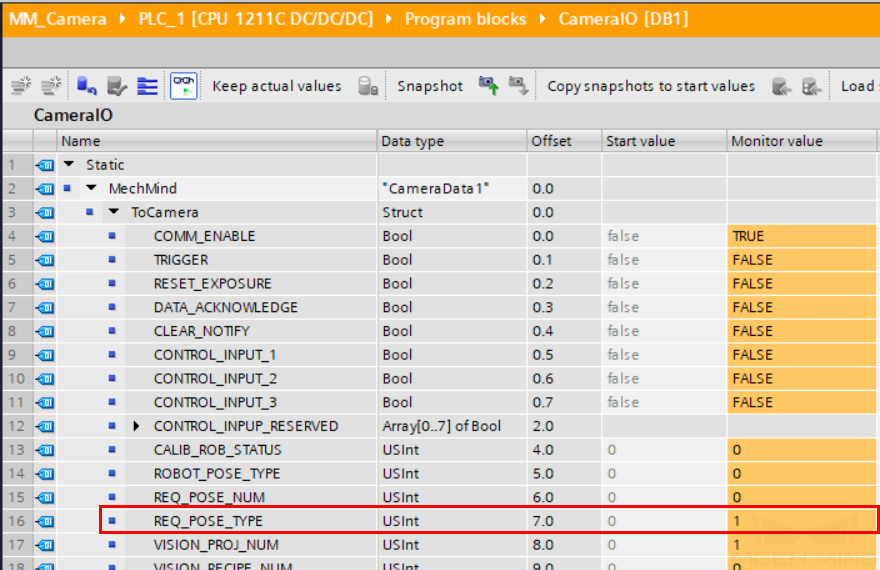
Set data type: in the CameraIO DB, change the monitor value of REQ_POSE_TYPE to 1. This asks Mech-Viz to send joint positions (instead of TCP data).
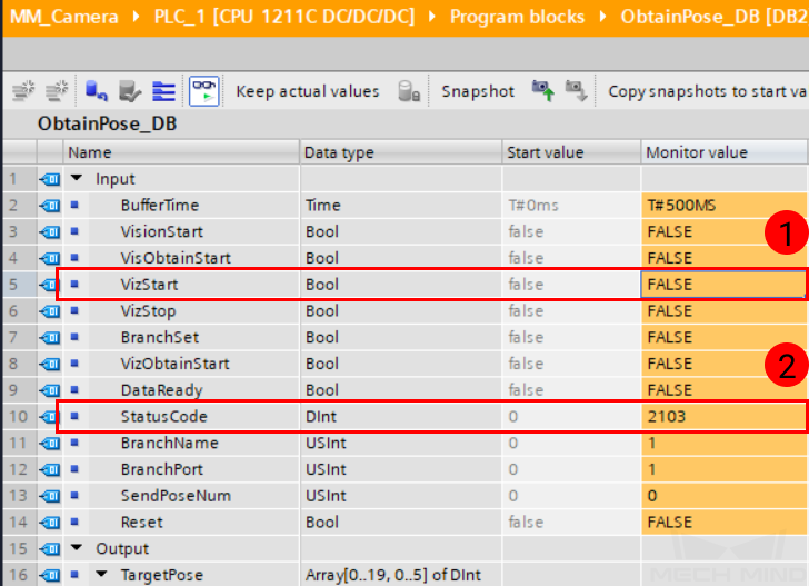
Start the Mech-Viz project: in the ObtainPose_DB DB, double-click on the monitor value of VizStart to change it to TRUE. Then, reset the monitor value to FALSE.
Check returned status code: check the monitor value of StatusCode. 2103 represents that the Mech-Viz project was started successfully. For other values, please refer to Status Codes for the corresponding error.
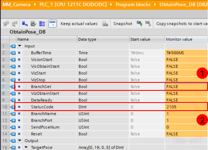
Select branch in the Mech-Viz project: in the ObtainPose_DB DB, double-click on the monitor value of BranchSet to change it to TRUE. Then, reset the monitor value to FALSE. This asks the Mech-Viz project to proceed along the branch set in step 2.
Check returned status code: check the monitor value of StatusCode. 2105 represents that the branch was selected successfully. For other values, please refer to Status Codes for the corresponding error.
Obtain planned path from the Mech-Viz project: in the ObtainPose_DB DB, double-click on the monitor value of VizObtainStart to change it to TRUE. Then, reset the monitor value to FALSE.
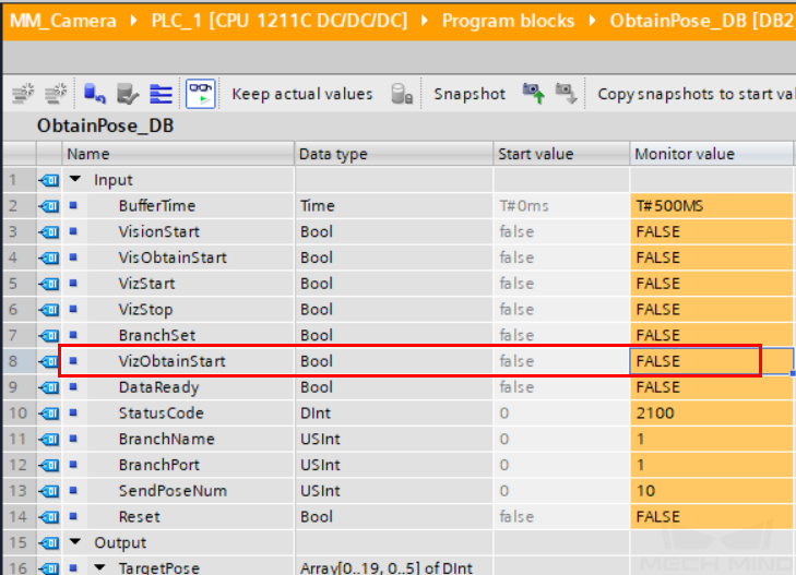
Check the received target points: the monitor value of SendPoseNum shows how many target points were received, and the target points are stored in TargetPose. Divide the monitor values by 10000 to obtain the actual pose data.