EtherNet/IP - KEYENCE PLC
This section provides information on setting up communication between a KEYENCE PLC and Mech-Mind Software Suite via EtherNet/IP.
Overview
Hardware and Software Requirements
Hardware
KEYENCE PLC:
KV-8000 series
KV-8000A
KV-7500
KV-5500
Other models with a KV-EP21V or KV-NC1EP EtherNet/IP Unit
USB Type A Male to Type B Male cable
AC 220 V to DC 24 V power adapter
HMS IXXAT INpact EIP Slave PCIe interface card installed on the IPC in Mech-Mind Vision System
Switch
Ethernet cables
Attention
A KV-8000 model is used in the example below.
Software
KEYENCE PLC programming software KV STUDIO V11.41
Mech-Mind Software Suite: Mech-Center 1.5.1 or above, Mech-Vision 1.5.0 or above, and Mech-Viz 1.5.0 or above
VCI V4 (driver software for HMS IXXAT INpact 40 interface card)
Mech-Mind EDS file:
File name: 005A002B003A0100.EDS
Location:
Mech-Mind/Mech-Center/mech_interface/EthernetIP
Example programs:
CameraSignalsMove.mod
CameraTest.mod
ObtainPose.kfb
The files are stored in
Mech-Mind/Mech-Center/mech_interface/documents/CN/基恩士EtherNet IP编程指南. Please copy and paste all files to the computer with KV STUDIO installed.
Note
Connect the Mech-Mind Vision System IPC, computer with KV STUDIO installed, and PLC to the same router.
Configure IPC and Initiate Communication
Check PCI-e Card and Driver Software
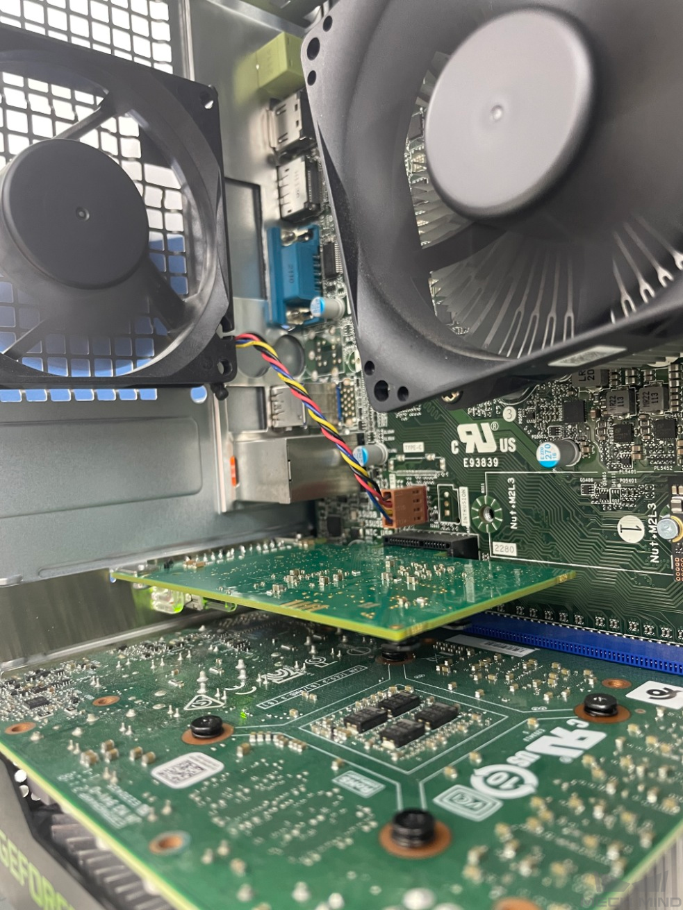
Please make sure that the INpact EIP Slave PCIe interface card has been pressed into the PCI-e slot of the IPC, as shown below.
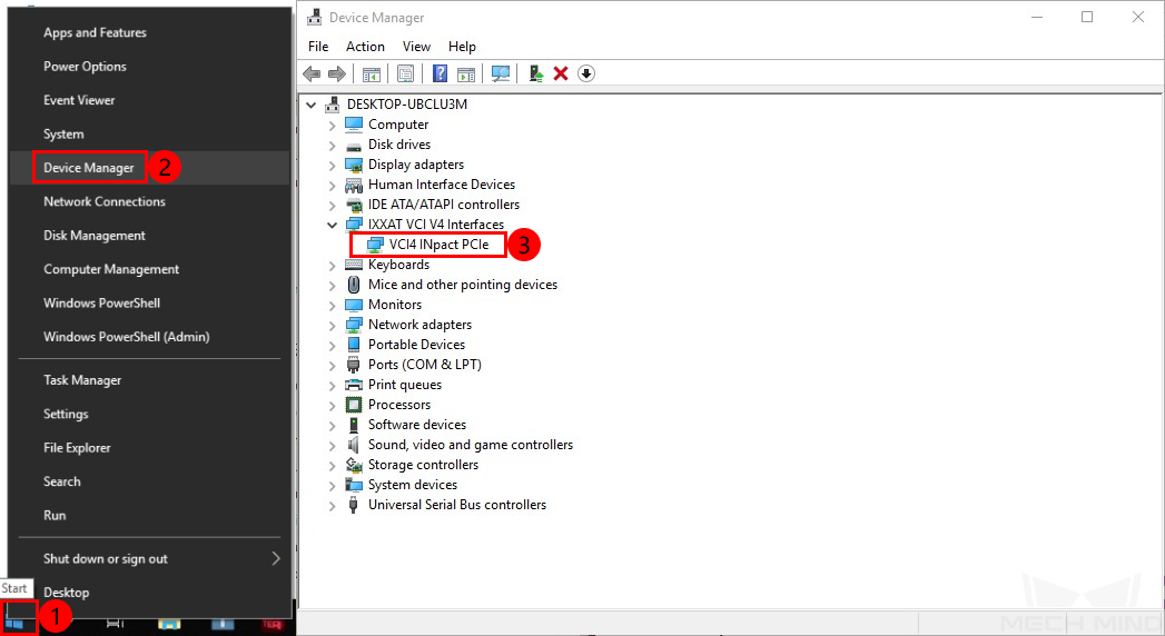
Start the IPC, go to and check if the driver software VCI4 INpact PCIe has been installed.
Configure Mech-Interface in Mech-Center
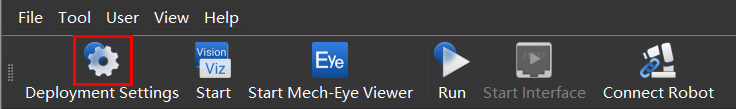
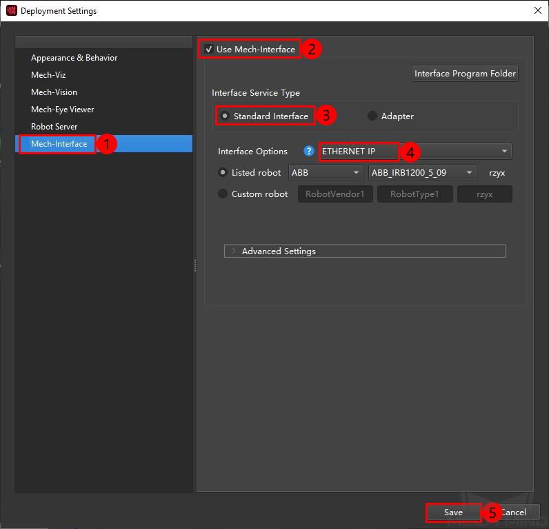
Open Mech-Center, and click on Deployment Settings.
Go to Mech-Interface, check Use Mech-Interface and select . Click on Save to complete configurations.
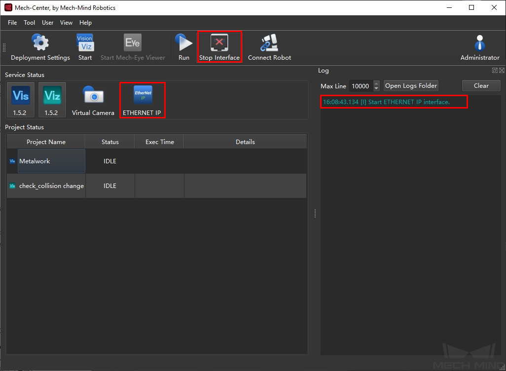
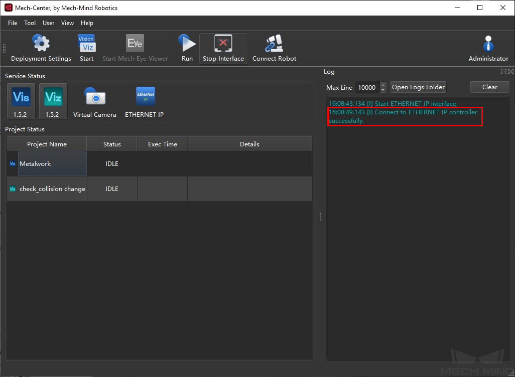
Click on Start Interface in the Toolbar. Then an ETHERNET IP icon will display in the service status bar.
Configure IP address of the PCI-e Card
Download and install HMS IPconfig software on the IPC first. Use an Ethernet cable to connect the network ports of the IPC and the INpact EIP Slave PCIe.
Attention
After configurating the IP and initiating communication successfully, the Ethernet cable used here can be removed.
Open HMS IPconfig, click on
 and select Ixxat INpact EtherNet/IP(TM). Then uncheck Retrieve IP settings dynamically from a DHCP server and enter the IP address and subnet mask, as shown below. After configuration, click on Apply.
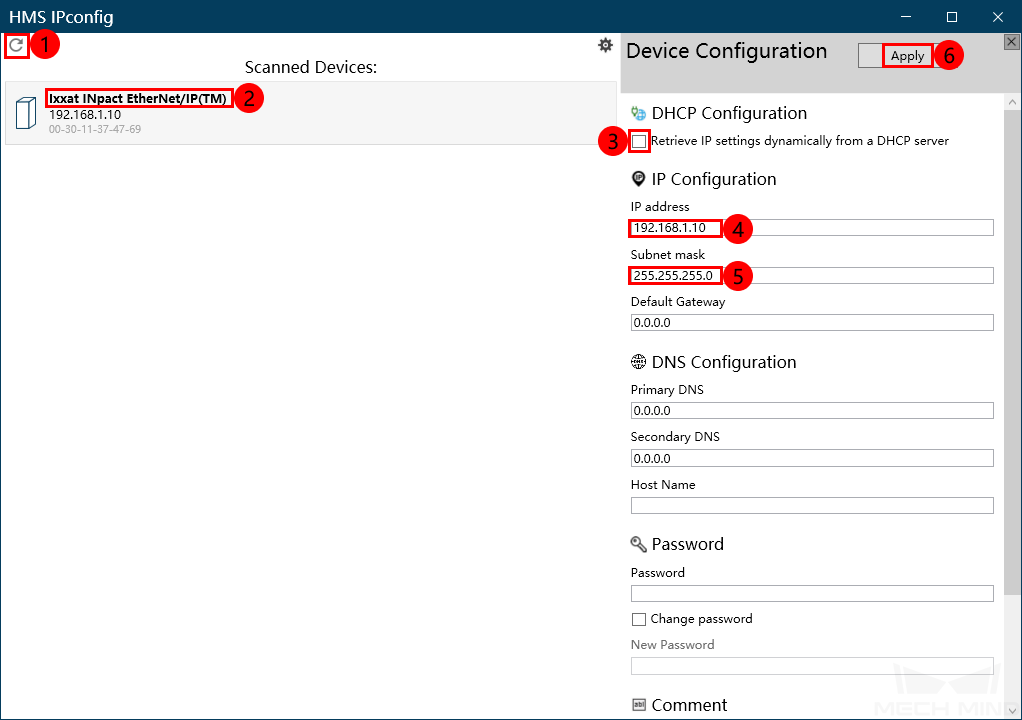
Attention
The IP address should be the same as which is configured in the PLC.
Install EDS file and Configure Communication
Create PLC Project
Open KV STUDIO, click on
 , select the PLC model according to the model in use, and name the project. Then click on Refer to select a location to store the project, and click on OK to save settings.
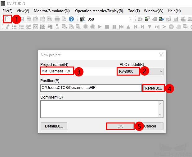
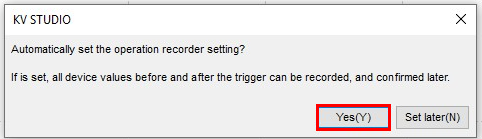
If the message “Automatically set the operation recorder setting?” pops up, select Yes.
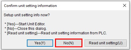
If the message “Setup unit setting info now?” pops up, select No.
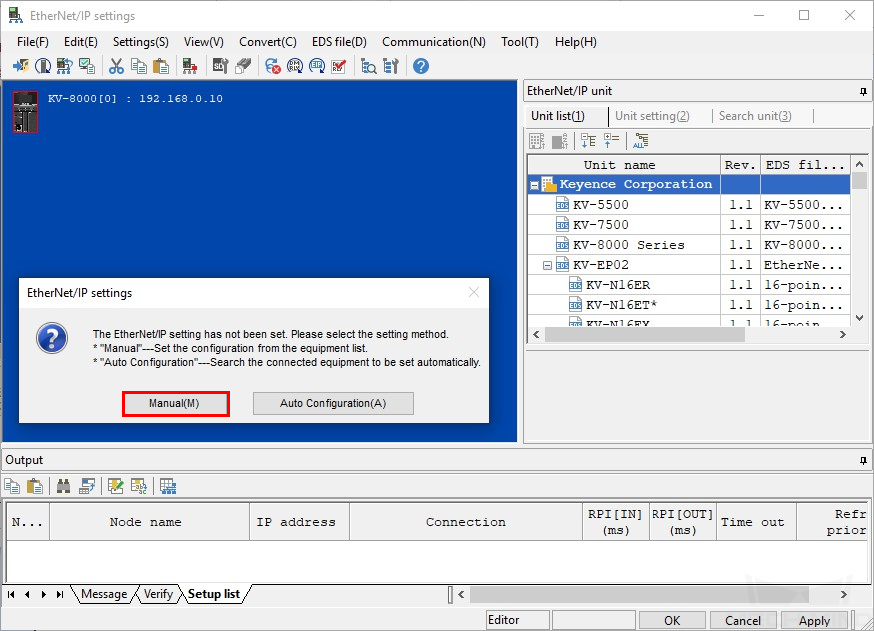
Go to , double click on EtherNet/IP R30000 DM10000.

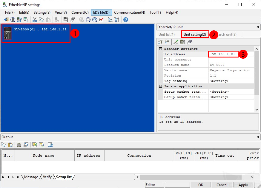
An EtherNet/IP settings window will appear as shown below. Select Manual in the pop-up window.
Select KV-8000, click on Unit setting and then set the IP address of the PLC.
Install EDS File and Configure Network
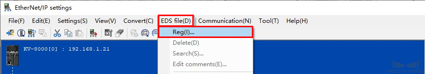
Click on EDS file in the EtherNet/IP settings window, and select Reg. An Open window will pop up.
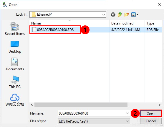
Locate and select the EDS file and click on Open.
Attention
The EDS file is stored in the folder where Mech-Center is installed. The default path is
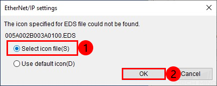
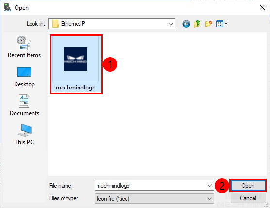
Mech-Mind/Mech-Center/mech_interface/ETHERNETIP. If KV STUDIO is not installed on the same IPC where Mech-Center is installed, you can copy and paste the ETHERNETIP folder to the PC with KV STUDIO installed.If the message “The icon specified for EDS file could not be found.” pops up, select Select icon files and then click on OK.
After selecting the icon files, click on Open.
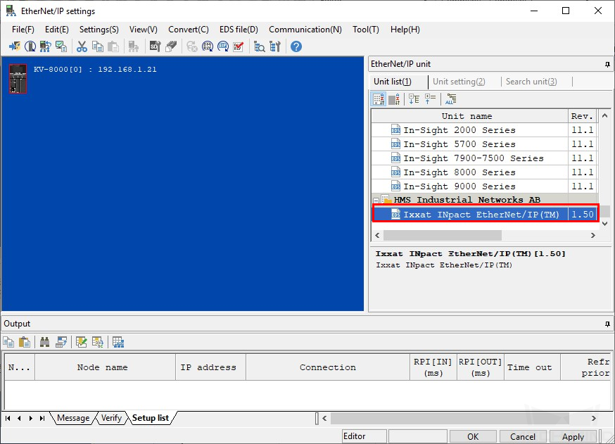
If the EDS file is registered successfully, Ixxat INpact EtherNet/IP(TM) will appear in the Unit list. Double click it to connect to the EtherNet/IP network.
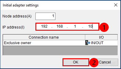
Set the IP address in the Initial adapter settings window, set the IP address of the IPC as same as which is set in HMS IPconfig, and then click on OK.
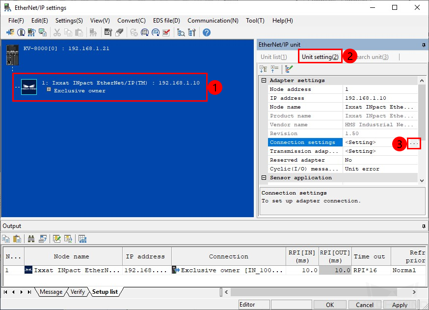
Select Ixxat INpact EtherNet/IP(TM), click on Unit setting(2) and then click on .. next to Connection settings.
Now you can see a Connection settings window. Click on Assign device and then assign the IN and OUT manually, as shown below. Go back to the EtherNet/IP settings window after assigning.
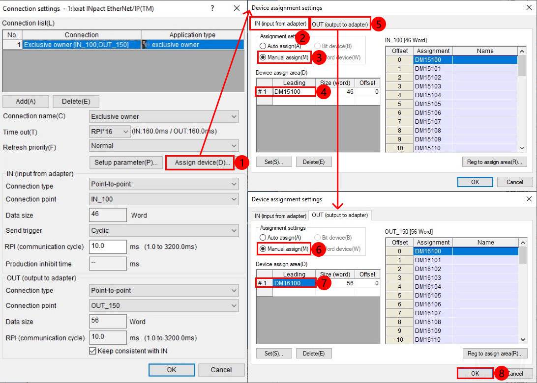
Note
The Input and Output in the figure are applicable to this example only.
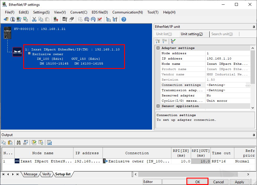
Now the information of the server appear in the EtherNet/IP settings window. Click on OK.
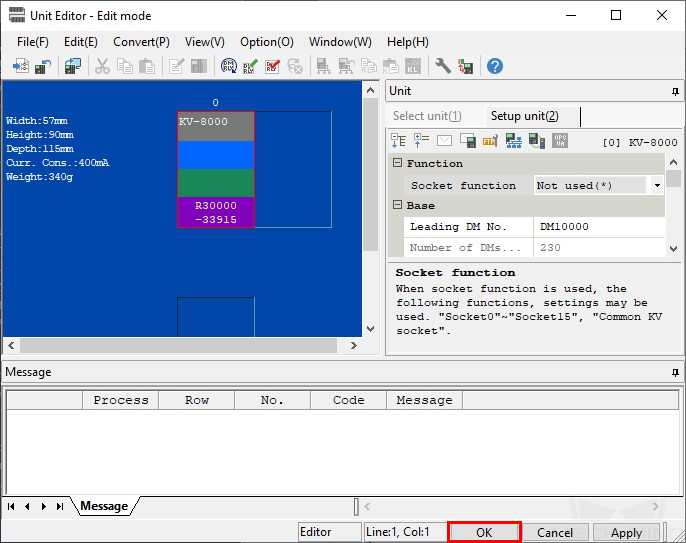
Click on OK in the Unit Editor window.
Download Hardware Configuration to PLC
Go back to the main interface of KV STUDIO, click on
 button in the menu bar.
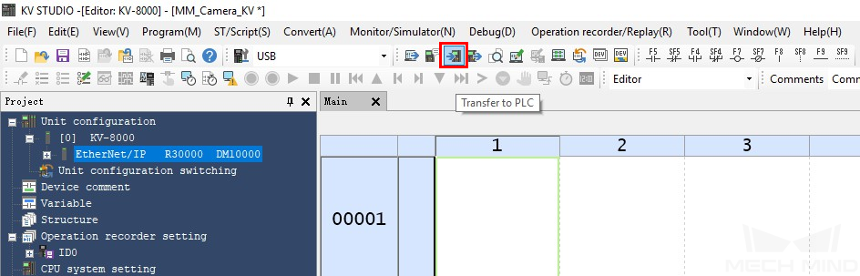
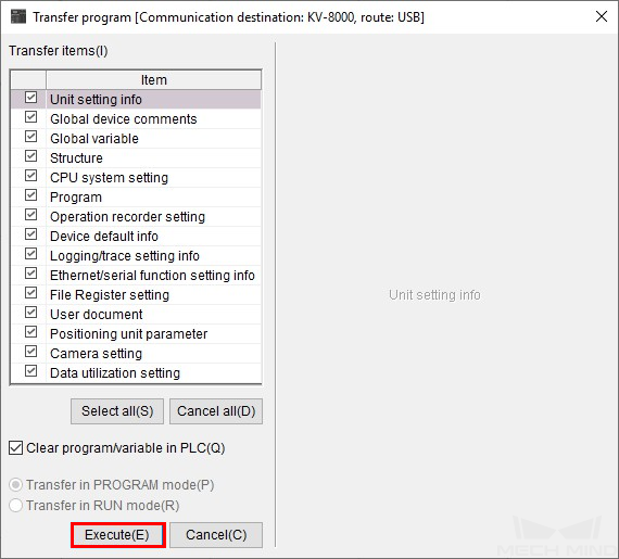
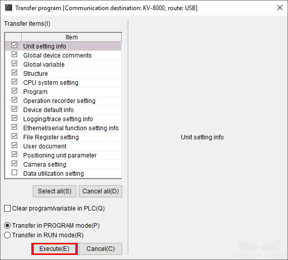
Keep the default settings, and click on Execute in the Transfer program window.
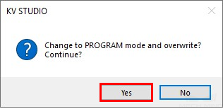
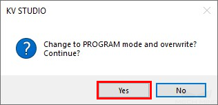
Select Yes in the pop-up window showing the message “Change to PROGRAM mode and overwrite?”.
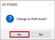
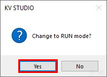
Select Yes in the pop-up window showing the message “Change to RUN mode?”.
Check Communication
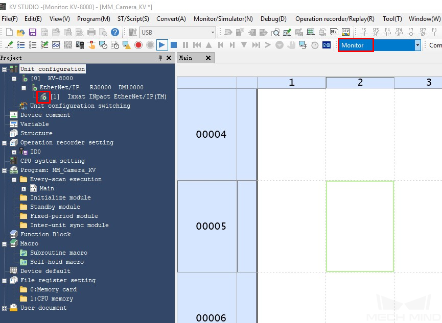
If the PLC is connected successfully, the status of Ixxat INpact EtherNet/IP(TM) will be displayed as online in Monitor mode.
The PLC is successfully connected to Mech-Center if the following message is displayed in Mech-Center Log panel:
Connect to ETHERNET IP controller successfully
Note
If you don’t see this log message, please check if:
The hardware are properly connected;
If Mech-Interface has been started by clicking on Start Interface in the Toolbar;
If the hardware configuration has been downloaded to the PLC.
Import Example Program and Download to PLC
Note
Before you add the example program to a project already in use, it is recommended to import it to a new project and test it first. In the following steps, the project created earlier is used to import and test the example program.
Import Example Program Files
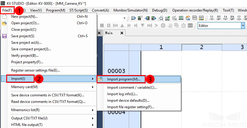
In the main interface of KV STUDIO, go to .
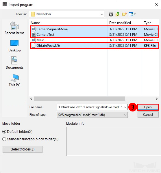
In the pop-up Import program window, select the CameraSignalsMove.mod, CameraTest.mod, and ObtainPose.kfb files, and then click on Open.
Click on OK in the Import completed window.
Download PLC Program
Go back to the main interface of KV STUDIO, click on
 button.
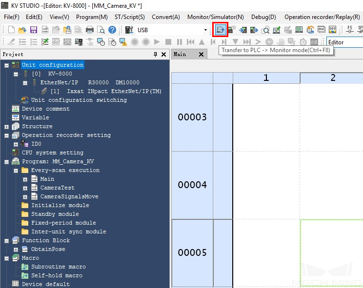
Keep the default settings, and click on Execute in the Transfer program window.
Select Yes in the pop-up window showing the message “Change to PROGRAM mode and overwrite?”.
Select Yes in the pop-up window showing the message “Change to RUN mode?”.
Test with Mech-Vision/Mech-Viz Project
This section introduces how to run the Mech-Vision/Mech-Viz project and obtain data from the project using the ObtainPose FB. For detailed information on the modules, please refer to PROFINET.
Prerequisites
Mech-Vision project(s):
Executable
Set to autoload
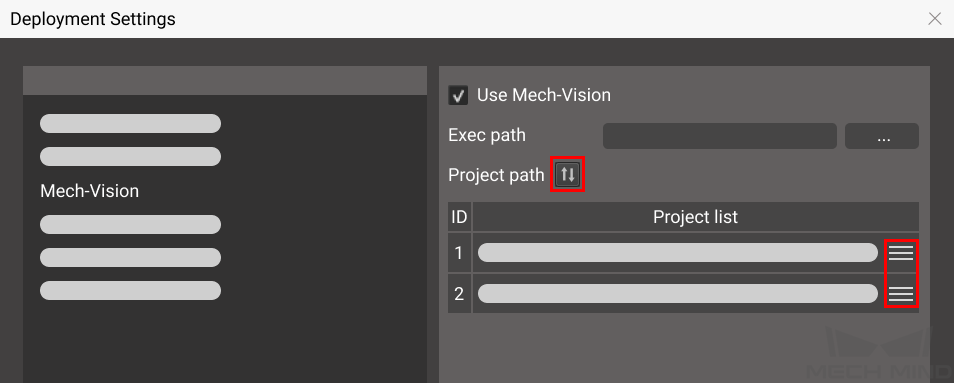
The Project list in is synced by clicking on
 , and the order of Mech-Vision projects have been adjusted according to actual needs.
Mech-Viz project:
Executable
Set to autoload
Contains a branch_by_service_message Task that has been renamed to 1.
Run Mech-Vision Project and Obtain Vision Points
Parameter Settings
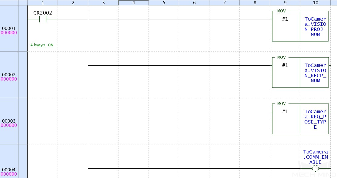
Set the ToCamera.COM_ENABLE to be always ON.
Double click on the MOV module, set the Mech-Vision project ID the same as the one set in Deployment Settings in Mech-Center. For example, if the monitor value is changed to 1, then Mech-Vision project No. 1 in the Project list of Mech-Center will be started.
Set the number of vision points to be sent by Mech-Vision. The default value of REQ_POSE_NUM is 0, which means the Mech-Vision project will send all the vision points.

Start Mech-Vision Project
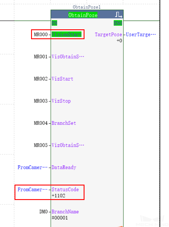
Go back to main interface of KV STUDIO, go to and double click on CameraTest. Double click on VisionStart in the FB ObtainPose to set the value to 1 and therefore start Mech-Vision project. Then double click again to reset the value to 0.
Check returned status code: check the monitor value of StatusCode. 1102 represents that the Mech-Vision project was started successfully. For other values, please refer to Status Codes for the corresponding error.
Obtain Vision Points from Mech-Vision
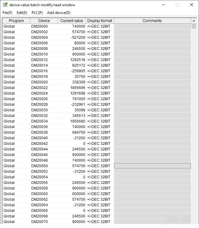
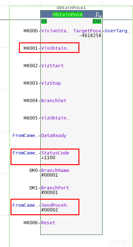
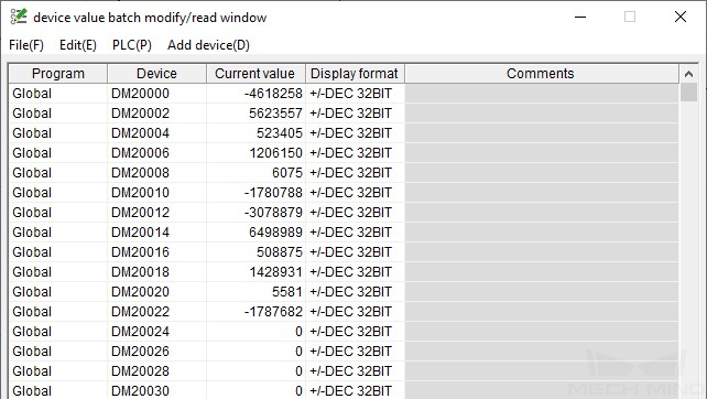
After the status code 1102 is returned, double click on VisObtainStart in the FB ObtainPose to set the value to 1 and therefore obtain vision points from Mech-Vision. Then double click again to reset the value to 0. The result is shown as below. The value of SendPoseNum is 2, which means 2 vision points are obtained from Mech-Vision.
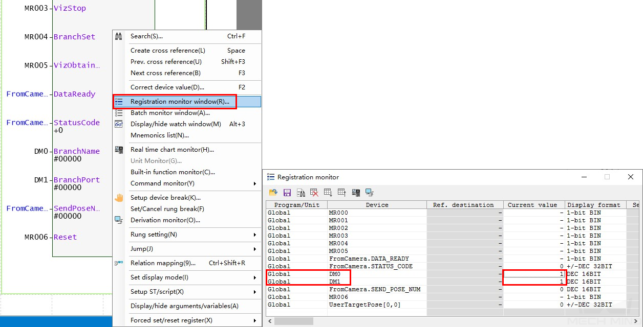
In the main interface of KV STUDIO, click on
 button to open the device value batch modify/read window.
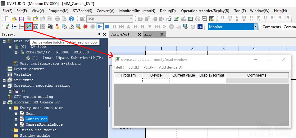
Select and configure the device, leading No., Number, and Display format. Click on OK after configurations.
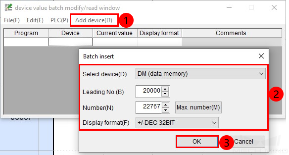
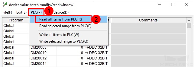
Select .
Hint
This example received 2 poses. Divide the transferred values by 10000 to obtain the actual pose data.
Run Mech-Viz Project and Obtain Planned Path
Parameter Settings
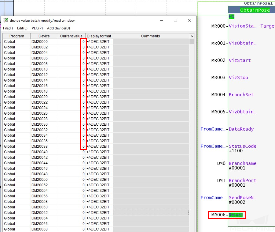
Double click on Reset in the ObtainPose FB to set the value to 1. Then double click again to reset the value to 0.
Hint
Open the device value batch modify/read window to check if the previously obtained vision data has been cleared successfully.
Modify the value of DM0 register, set the value of BranchName to 1.
Modify the value of DM1 register, set the value of BranchPort to 1 , the Mech-Viz project will proceed along out port 1 of Task 1.
Set the value of REQ_POSE_TYPE to 1. This asks Mech-Viz to send joint positions (instead of TCP data).
Start Mech-Viz Project
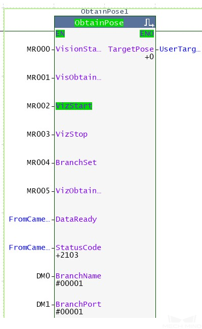
Double click on VizStart in the ObtainPose FB to set the value to 1 and therefore start Mech-Viz project. Then double click again to reset it to 0.
If the value returned by the variable StatusCode is 2103, it represents that the Mech-Viz project was started successfully. For other values, please refer to Status Codes for the corresponding error.
Select Branch in the Mech-Viz Project
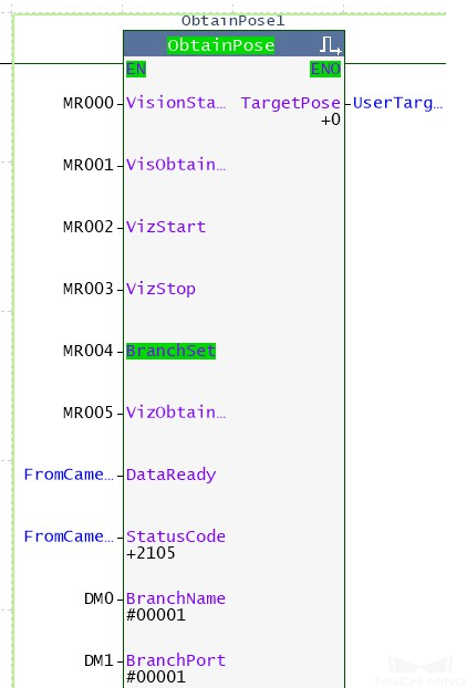
Double click on BranchSet in the ObtainPose FB to set the value to 1 and therefore select branch in the Mech-Viz project. Then double click again to reset it to 0.
If the value returned by the variable StatusCode is 2105, it represents that the branch was selected successfully. For other values, please refer to Status Codes for the corresponding error.
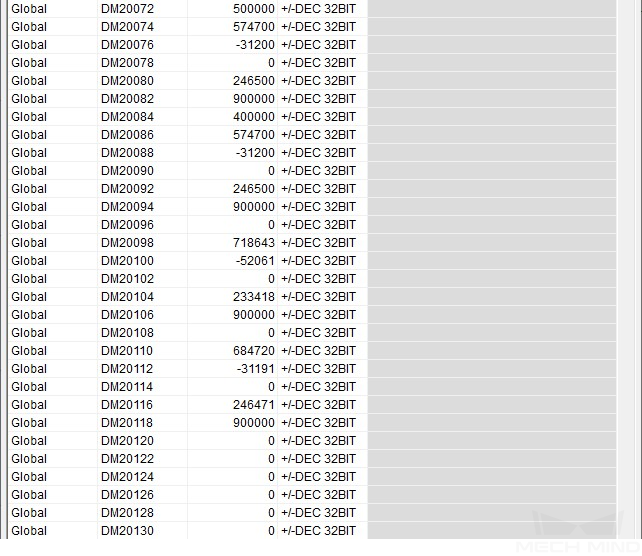
Obtain Planned Path
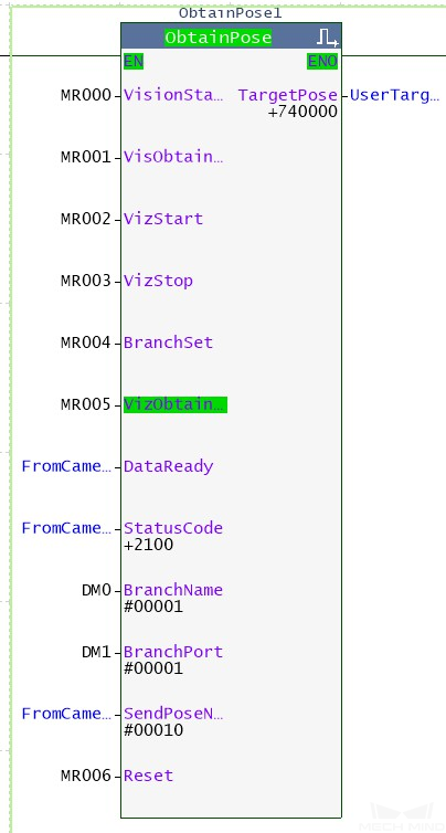
Double click on VizObtainStart in the ObtainPose FB to set the value to 1 and therefore obtain planned path from Mech-Viz project. Then double click again to reset it to 0.
If the value returned by the variable StatusCode is 2100, it represents that planned path was obtained successfully. For other values, please refer to Status Codes for the corresponding error. The value of SendPoseNum shows how many target points were received, and the target points are stored in TargetPose.
Go back to device value batch modify/read window, the 10 poses are shown as below. Please divide the transferred values by 10000 to obtain the actual pose data.