Adapter Generator
The adapter generator is a component integrated in Mech-Center.
Use the Adapter generator to get an Adapter that only sends visual points through a series of settings. If the actual situation is complicated, you can simply modify the generated code to meet the actual needs according to the actual situation.
The following will introduce how to use the Adapter generator.
Tip
For the convenience of configuration, the corresponding component has its detailed description. You can hover the mouse cursor over the component to view it.
How to Use the Adapter Generator
Adapter Generator Location
The location of the Adapter generator is as follows Figure 1as shown.
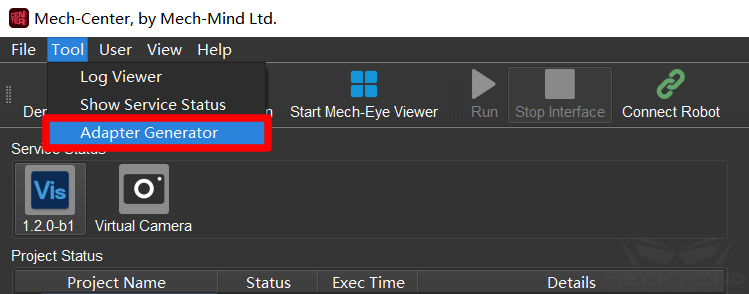
Figure 1 Adapter generator location
Network Configuration-Server or Client
In this step, you need to set the name of the Adapter, the Client or Server, and the communication format. The interface is shown in Figure 2. Click Next in the lower right corner when finished.
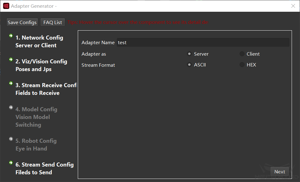
Figure 2 Network configuration-Server or Client
Choose Server or Client: You need to configure the corresponding adapter host IP and port in Settings.
Bind port: It only takes effect in Client mode. If the Server has port restrictions on the Client, check this option.
Select the communication format: The options are ASCII string and hexadecimal. Hexadecimal (HEX) needs to specify the endianness.
Mech-Viz/Mech-Vision Configuration-Pose and Joint Angle
This step is to set the number and form of poses. The interface is shown in Figure 3. Click Next in the lower right corner when finished.
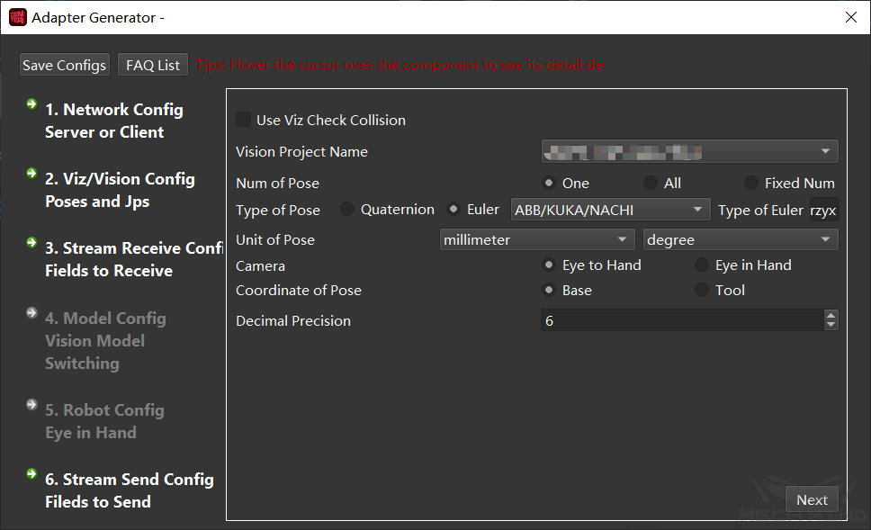
Figure 3 Mech-Viz/Mech-Vision configuration-pose and joint angle
Vision project Name: It is necessary to configure the Vision program path and Vision project path in Settings in advance.
Num of Pose: Select the number of poses to be sent to the other party.
Type of Pose: You can choose quaternion or Euler angle.
Unit of Pose: Use millimeters and degrees in general situation.
Camera: Choose the camera installation method. There are three methods which are ETE, ETH and EIH.
Coordinate of Pose: Determine which coordinate system the sent Pose point is based on. In general, Pose is based on the Base Coordinate System. Pose can only be based on the Tool Coordinate System if the robot unable to give the end pose of the robot when in EIH.
Decimal Precision: Determine the decimal places of the sent Pose point. The maximum number of digits is 10.
Use Mech-Viz Check Collisions: After checking it, the visual points are calculated by Mech-Viz detection, filtering the points that failed in the planning, and filtering out the collision-free grasping poses. This option requires Mech-Viz to create a project. The Mech-Viz project needs to be at least from the home point to visual_move. You can refer to the example project check_collision in /tool/viz_project under the Mech-Center installation path.
Attention
As shown in the sample project, the photo is triggered by visual_look, and non-moving tasks must exist, and the name cannot be changed, including: notify_1, notify_2, visual_look_1.
Mech-Viz Config for Generator: The interface appears after clicking “Use Mech-Viz to Check Collisions”, as shown in Figure 4. Click Save in the lower right corner when finished.
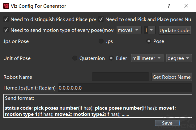
Figure 4 Mech-Viz config settings
Need to distinguish Pick and Place poses: pick points are all points before visual movement (including visual movement), and placement points are all points after visual movement. In some scenarios, robots may need to distinguish between grabbing actions and placing actions according to their tasks.
Need to send Pick and Place poses Number: If the number of points is large, you can bring the quantity field of the pick points and placement points. After checking, this field will be brought only if the default number of points is greater than one.
Need to send motion type of every pose: The motion mode of the mobile task in Mech-Viz is divided into joint motion or linear motion.
Update Code: The default joint motion corresponding code is 1, and the linear motion corresponding code is 2. The code can be customized, and the updated value will take effect after the change.
Jps or Pose: The way to send pose, Jps is used by default. If you choose Pose, you need to check Send tool pose in the “Other” tab in Mech-Viz. As shown in the figure:
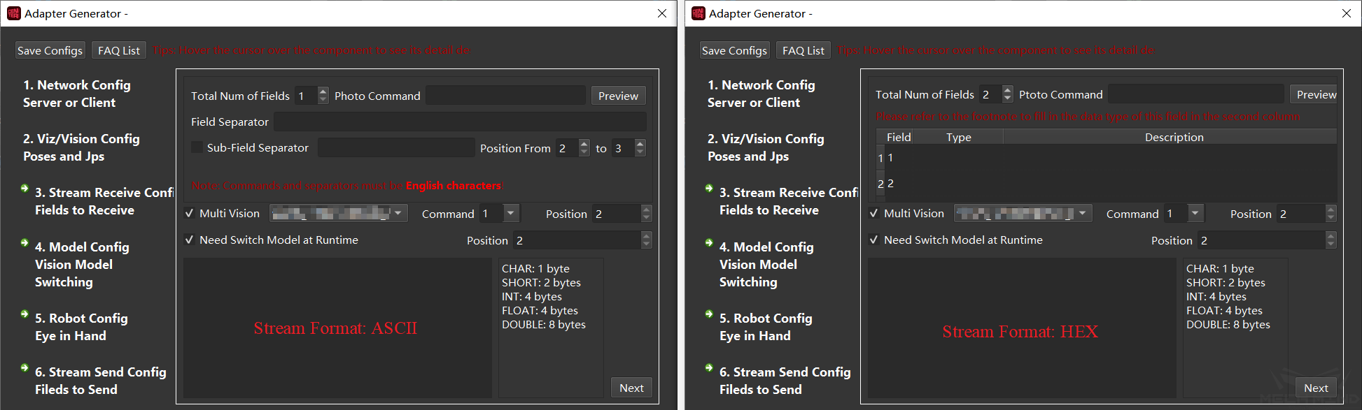
Figure 5 Setting the pose of the sending tool
Unit of Pose: Set the corresponding unit according to the selected sending format. The unit is generally degrees and millimeters.
Robot Name: Using Mech-Viz to simulate robot motion requires a real robot service. The generated Adapter will simulate this service. The robot name is the name of the service and needs to be consistent with the robot name in Mech-Viz. You can load the project in Mech-Viz and check Automatically load current project, then return to the settings and click Get robot name to successfully add the robot name.
Home Jps(Unit: Radians): It refers to the reference origin of the movement in Mech-Viz, the unit is radians, separated by commas. You can edit a movement from Mech-Viz as the origin and copy the joint position of the origin.
Receiving Data Format Configuration-receiving Field
This step is to set the format of the receiving field. The interface is shown in Figure 6. What needs to be set are: photo instruction, multiple projects (instruction code), dynamically switch templates (template instruction code), as well as the total number of fields, field types, field separators and sub-field separators. Click Next in the lower right corner when finished.
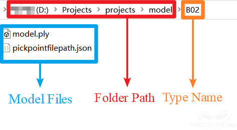
Figure 6 Received data format configuration-receive field
Photographing instruction: External send a photographing instruction to the Mech-Mind Software Suite, so that the camera can take photos. When the communication format is ASCII code, it is recommended to use letters, such as letters p and the field position is 1 by default. When the communication format is hexadecimal (HEX), an integer in hexadecimal form is required, such as 0xff or ff.
Multiple projects (instruction code): This setting is optional. When there are multiple Vision projects in a project, different Vision projects need to be called according to external instructions, and the instruction code is configurable.
Note
Each project corresponds to a unique command code, and the field position is unique, and cannot overlap with other fields.
Need to dynamically switch the template (template instruction code): this setting is optional. The dynamic switch template means that the object to be recognized has multiple models, and the template file of the current model needs to be dynamically switched during operation.
Note
The field position is unique and cannot overlap with other fields.
Total number of fields: related to the number of parameters that need to be set, and the value range is 1~10. There must be a camera instruction in the field.
Field type: It needs to be set when the communication format is hexadecimal (HEX). The available types are CHAR, SHORT, INT, FLOAT, DOUBLE.
Field separator and sub-field separator: They need to be set when the communication format is ASCII. If there are more than two fields, you need to fill in the field separator; if there are additional separators in the additional information, the sub-field separator is also necessary, and you can specify the start and end range of the sub-field.
Template Configuration-Vision Template Switching
When the Need to dynamically switch templates option is checked in the previous step, this configuration needs to be set. Click Next in the lower right corner when finished.
Template folder: The folder where templates are stored according to the type. The folder hierarchy is shown in Figure 7.
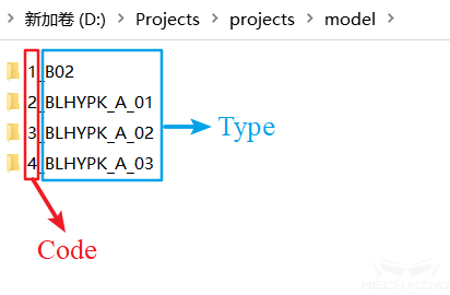
Figure 7 Template folder
Type and type code: After loading the template folder, all types under the folder will be parsed into the type drop-down box. If you need the corresponding type code, please name the template subfolder according to the rule: code_type, as shown in the figure below:
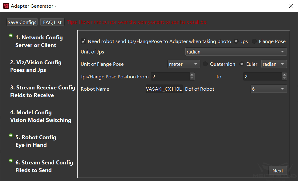
Figure 8 Type and type code
Switching templates on the interface: After selecting and starting the Adapter, a sub-interface will be generated, and the templates can be switched manually.
Step name: Need to set the name of the Step of the template, which means the step name of the corresponding step in Mech-Vision.
Step type: It indicates the type of corresponding step, currently only supports 3D Coarse Matching, 3D Fine Matching, 3D Coarse Matching (Multiple models), 3D Fine Matching (Multiple Models), Map to Multi Pick Points, Read Object Dimensions, Read Poses from File, Add Labels to Poses, each step type has corresponding attributes, and you can select attributes according to your needs.
After selecting attributes, click + or - to add or delete steps.
Attention
In order to name the template files uniformly, please name the template files with these attribute names. For example, the point cloud template file, please name it modelfile.ply, and the pick point please name it pickpointfilepath.json, and it is not case-sensitive.
Robot Configuration-Eye in Hand
In the case of Eye in Hand, if the customer needs us to provide a Pose based on the Base coordinate system, the robot needs to provide the joint angle or flange posture when taking pictures. This step will set the pose format of the robot when taking pictures. The interface is shown in Figure 9. Click Next in the lower right corner when finished.
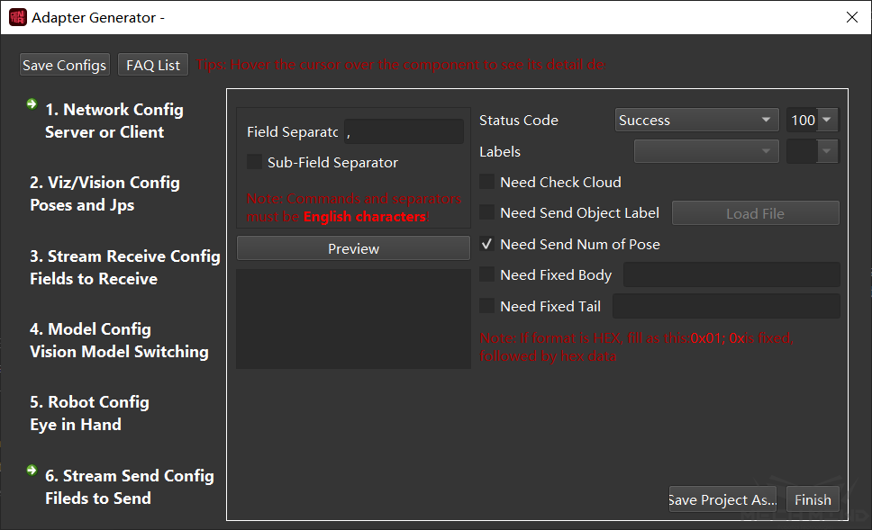
Figure 9 Robot configuration-Eye in Hand
Pose form: You can choose joint angle or flange pose.
Joint angle unit: Degree or radian can be selected.
Flange pose unit: Position can choose meters or millimeters, attitude (rotation) can choose quaternion or Euler angle, Euler angle unit can choose degrees or radians.
Joint angle/flange attitude field position: It is the position of the start and end fields of the pose in the total field.
Attention
The index position starts counting from 1, and the index position 1 is the camera instruction!
Robot name: The name used to identify the robot service, which needs to be consistent with the robot name in Mech-Viz.
Robot degree of freedom: currently supports 4-axis and 6-axis robots, select the corresponding robot degree of freedom according to the actual project.
Send Data Format Configuration-send Field
This step is to set the format of sending Pose. The interface is shown in Figure 10. Click Next in the lower right corner when finished.
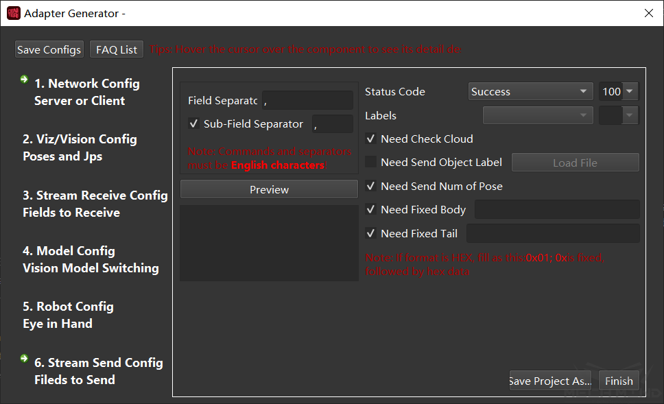
Figure 10 Sending data format configuration-sending field
Field Separator and sub-field separator: Set the separator form.
Status Code: Set the sending status, each status corresponds to a unique status code.
Need Check Cloud: After checking, the point clouds will be checked, if the point clouds does not exist, the corresponding status code will be output.
Need Send Object Labels: Sending object labels means to send to the other party according to the label recognized by Vision, each label is connected to the Pose; when the other party is inconvenient to parse the label string, you can also specify the code of the corresponding label, which needs to load the label file of all label strings. It should be noted that the label file format must be a json array format.
Need Send Num of Pose: Send the number of Pose of this time.
Need Fixed Body: When the vision is not recognized, send a message to the other party (the message after the error code).
Need Fixed Tail: After checking it, a fixed tail mark will be added after the data.
Attention
When the communication format is hexadecimal (HEX), it is necessary to set the status code, the number of poses, and the numeric type of poses.
After configuring all the above settings, click Finish or Save project as to save the Adapter.