Calibration Types, Methods and Scenarios
This section mainly introduces the types, methods and scenarios of the hand-eye calibration.
Calibration Types
According to the mounting method of the camera, the hand-eye calibration can be classified into:
ETH (Eye To Hand) calibration: This type calibrates the transformation relationship between the reference frames of the camera’s optical center and the robot base.
EIH (Eye In Hand) calibration: This type calibrates the transformation relationship between the reference frames of the camera’s optical center and the robot flange’s center point.
Attention
For ETH calibration, either the robot base or the camera moves, the extrinsic parameters would be altered, and the hand-eye relationship must be calibrated again.
For EIH calibration, if the camera moves relative to the flange, the extrinsic parameters would be altered, and the hand-eye relationship must be calibrated again.
According to whether the robot is controlled by the vision system, the hand-eye calibration can be classified into:
Automatic calibration (recommended): The robot is connected to the vision system, and the vision system controls the robot to automatically move according to the planed path and automatically capture images of feature points.
Manual calibration: The robot is connected to the vision system, and you need to manually move the robot for feature point capturing using the teach pendant and enter the robot pose.
Calibration Methods
The calibration method refers to the way to add calibration points for the hand-eye calibration. This software provides two calibration methods:
Multiple random board poses (recommended)
Using the paths generated by the software or the multiple poses added manually, this method captures images of calibration points at each waypoint on the paths in order to calculate the correct relationship between the calibration board, camera, and robot. It is easy to perform and has a high accuracy. It is recommended for 6-axis or 4-axis robots.
TCP touch
This method first determines the pose of the calibration board through the three-point method, and then establishes the spatial relationship among the calibration board, camera, and robot. This method is suited for situations where the robot is installed in a limited space and where the calibration board cannot be installed. It is recommended for 5-axis or other robots.
Tip
In actual application scenarios, determine the calibration method according the camera mounting method, robot type and robot activity space.
Calibration Scenarios
This section introduces calibration scenarios and their principles.
ETH Calibration Using the Multiple Random Board Poses Method
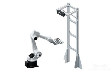
Figure 1. Calibration board location (ETH calibration using the multiple random board poses method)
Calibration board of known dimensions is installed on the robot flange, and the coordinates of each mark point on the calibration board, denoted by A, in the robot base coordinate system, can be obtained. By capturing images of the calibration board, the coordinates of the camera’s optical center relative to each mark point, denoted by B, can be obtained. The transformation relationship between the reference frames of the camera’s optical center and the robot base, denoted by X, is the unknown variable. Thus, A, B and X form a closed loop, and the value of X can be calculated through the equations generated from the loop. The spatial relationship between the calibration board and the robot flange, denoted by C, is unknown. Through movements of the calibration board during the calibration process, C can be obtained, which can be used to calculate A. Multiple poses of the calibration board can form a set of equations, which give an optimal value of X by numerical fitting and optimization algorithm. This is shown in the following figures.
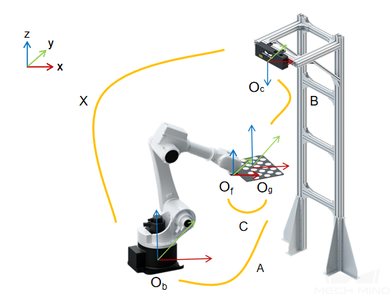
Figure 2. ETH calibration using the multiple random board poses method
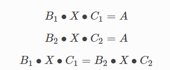
Figure 3. Equations for calculating the transformation relationship between the reference frames of the camera and robot
EIH Calibration Using the Multiple Random Board Poses Method
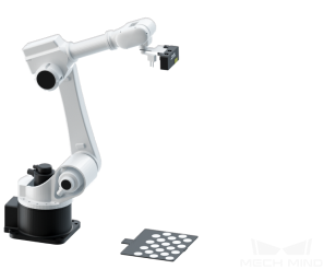
Figure 4. Calibration board location (EIH calibration using the multiple random board poses method)
In this scenario, the camera is mounted on a flange that is fixed at the end of the robot. The calibration board is placed within the camera’s field of view. The pose of the calibration board in the robot base reference system, denoted by A, is a measurable constant. The pose of the flange in the robot base reference system denoted by B, is a known variable. The spatial relationship between the camera’s optical center and each circle on the calibration board, denoted by C, can be calculated by capturing images of the calibration board with the camera. The spatial relationship between the center of the flange and the camera’s optical center, denoted by X, is an unknown constant. The above constants and variables are shown in the following figure. Thus, A, B, C, and X form a closed loop, as shown in the preceding Figure 3. Since A is a constant, when the first two equations are combined, X will be the only unknown variable. As the robot moves to different poses, the camera will capture images from different angles and produce multiple sets of A, B, and C. Then, these values can be used to perform numerical fitting and obtain an optimal solution of X.
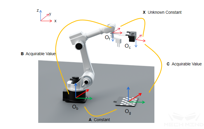
Figure 5. EIH calibration using the multiple random board poses method
For the equations used for calculating the transformation relationship between the reference frames of the camera and robot, see the preceding Figure 3.
ETH Calibration Using the TCP Touch Method
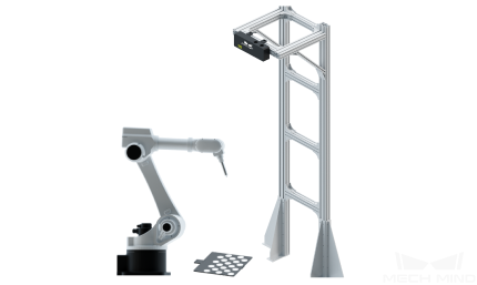
Figure 6. Calibration board location (ETH calibration using the TCP touch method)
When the TCP touch method is used, the calibration board is placed on the object plane and a sharp-tipped tool with known dimensions is installed on the robot flange. Then, touch the mark points on the calibration board with the center point of the tool by moving the robot. As shown in the following figure, the values of A and B are known, and the value of X can be obtained. When the calibration board is not fixed on the flange, the value of A can be calculated by touching the mark points on the calibration board using a sharp-tipped tool with known TCP coordinates.
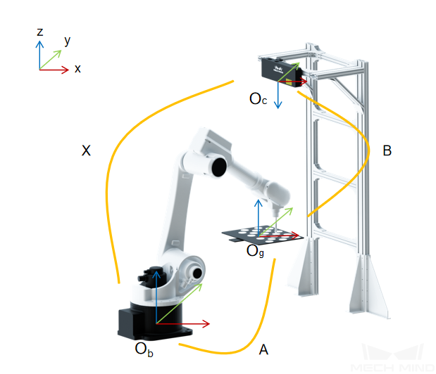
Figure 7. ETH calibration using the TCP touch method
For the equations used for calculating the transformation relationship between the reference frames of the camera and robot, see the preceding Figure 3.
EIH Calibration Using the TCP Touch Method
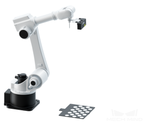
Figure 8. Calibration board location (EIH calibration using the TCP touch method)
When the TCP touch method is used, the calibration board is placed on the object plane and a sharp-tipped tool with known dimensions is installed on the robot flange. Then, touch the mark points on the calibration board with the center point of the tool by moving the robot. As shown in the following figure, since the values of A, B and C are known, the value of X can also be obtained.
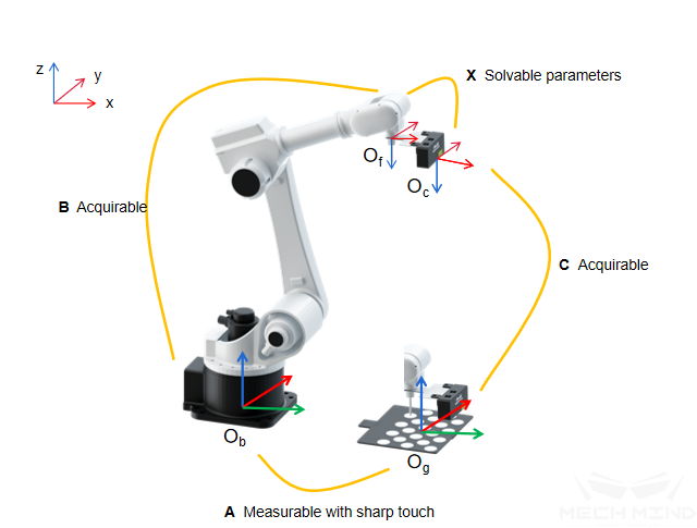
Figure 9. EIH calibration using the TCP touch method
For the equations used for calculating the transformation relationship between the reference frames of the camera and robot, see the preceding Figure 3.