Preparation for Calibration
Before the hand-eye calibration, you must complete the following preparations:
Connect the whole system.
Learn about the knowledge about the hand-eye calibration.
Mount or place the calibration board.
Adjust camera settings for point cloud generation of the calibration board
Connect the Whole System
Before the hand-eye calibration, you must connect each component of the Mech-Mind vision system and ensure their connectivity.
The hand-eye calibration requires the use of the Mech-Eye Viewer, Mech-Center, Mech-Vision and Mech-Viz software. Please update these software to the latest version.
In addition, please refer to Robot Integrations to complete the communication settings and connection of the robot, and ensure that the robot is connected in the Mech-Center software.
Learn About the Knowledge About the Hand-eye Calibration
Before the hand-eye calibration, you should get familiar with the basic knowledge of the hand-eye calibration, including its definition, types, methods, and scenarios.
Mount or Place the Calibration Board
To enhance the calibration efficiency, you need to mount or place the calibration board properly before the the hand-eye calibration.
Check that the currently used calibration board is a qualified one: its circles should be clearly visible and without obvious scratches or deformations.
Mount or place the calibration board properly.
In the scenario of ETH calibration using the multiple random board poses method, mount the robot-specific bracket for calibration board onto the robot flange, and then mount the calibration board onto the bracket. Make sure that the calibration board is attached securely, and that the board is parallel to the XY plane of the robot flange’s reference frame.
Note
If an undetachable end effector is connected to the robot flange, you can attach the calibration board directly to the end effector.
In other calibration scenarios, place the calibration board in the center of the object plane, where target objects are to be placed.
Note
Other calibration scenarios refer to:
EIH calibration using the multiple random board poses method
ETH calibration using the TCP touch method
EIH calibration using the TCP touch method
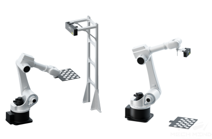
The following figure shows the mounting (on the left) and placement (on the right) of the calibration board.
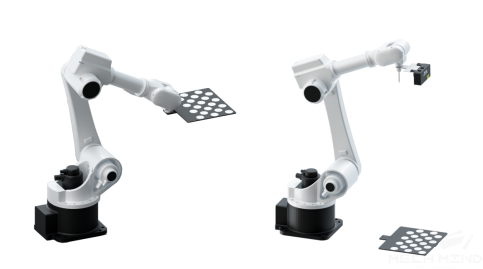
Move the robot to the starting point for calibration after you have mounted (on the left of the figure) or placed (on the right of the figure) the calibration board, as shown in the following figure.
When the calibration board is mounted, the starting point is the bottom center of the camera’s field of view (the robot will move up during calibration).
When the calibration board is placed, the starting point is the camera’s scanning position (the robot will move up during calibration).
Adjust Camera Settings for Point Cloud Generation of the Calibration Board
Open Mech-Eye Viewer and adjust camera settings by referring to Mech-Eye Viewer .
Adjust the settings in 2D Scanning section to make sure that the 2D image of the calibration board is clear and neither overexposed nor underexposed.
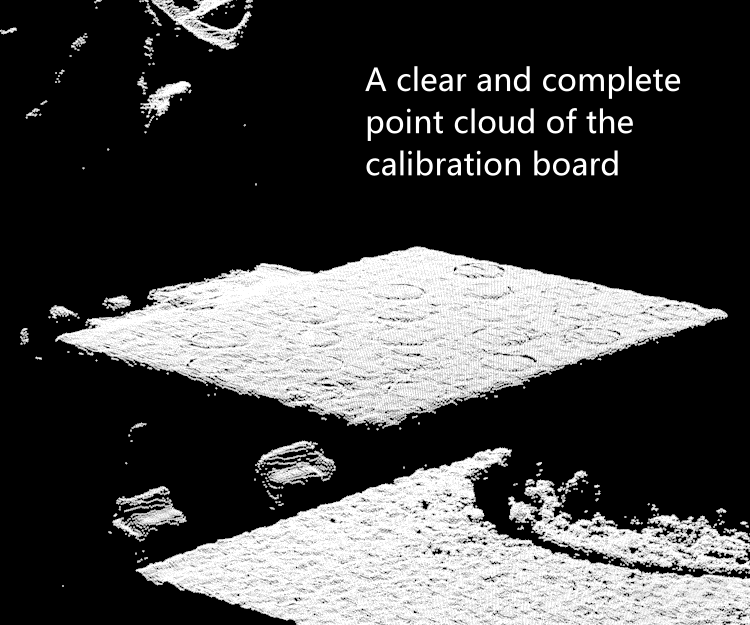
Adjust the settings in 3D Scanning section to make sure that the point clouds of the circles on the calibration board are complete and have clear contours.
Note
If the on-site ambient lights are not ideal and affects the quality of 2D images and point clouds, you can use shading or supplemental light to improve the lighting conditions.
Make sure the obtained point clouds of the circles on the calibration board are complete and have clear contours, as shown in the following figure.