ABB Calibration Program
This section introduces the process of calibrating the camera extrinsic parameters using the calibration program.
The process consists of 4 steps:
Before proceeding, please make sure that:
You have loaded the Standard Interface program onto the robot and can establish communcation with Mech-Center.
You are familiar with the contents in Hand-Eye Calibration Guide.
The calibration process introduced in this section is applicable to scenarios where standard interface is used to communicate and the extrinsic parameters need to be calibrated multiple times.
Calibration Process
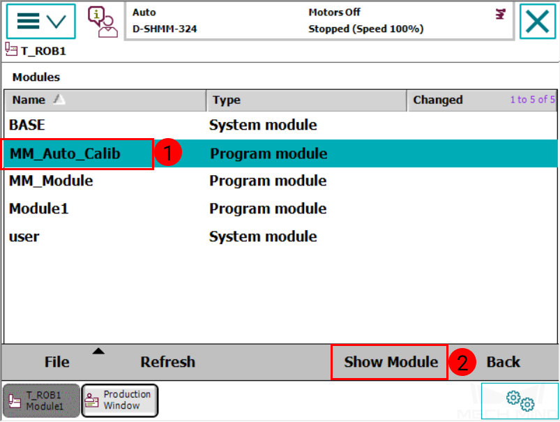
Select the Calibration Program
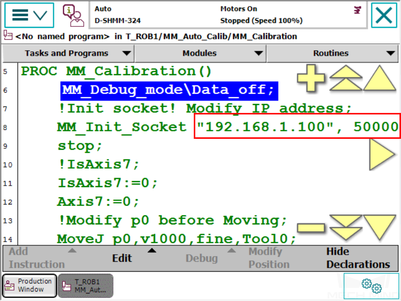
Select and open the program module MM_Auto_Calib in T_ROB1. Please make sure that the IP address in the program is the same as that of the IPC, and the port number is set correctly.

Teach the Calibration Start Point
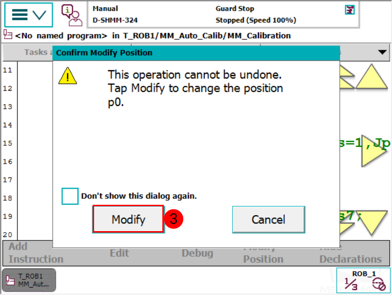
Move the robot to the start point for the calibration, and then modify this position as P0. Press on Modify in the pop-up window to confirm.
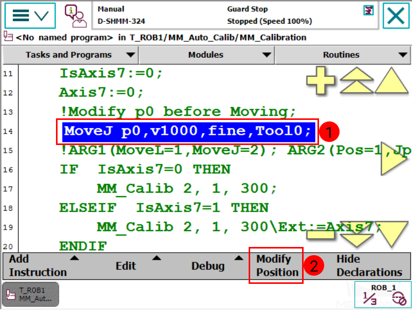
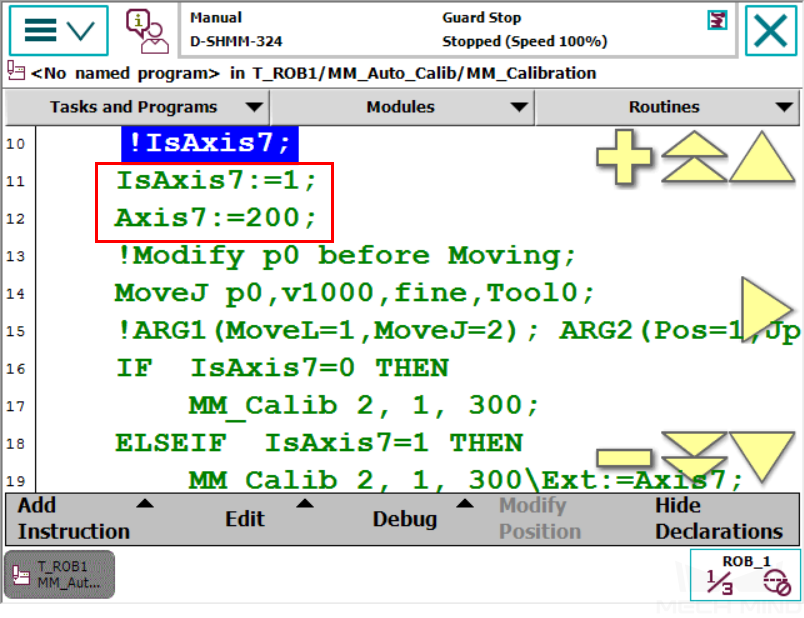
If the 6-axis robot is installed on a guide rail that is controlled by the robot, please set IsAxis7: =1, and configure the value of Axis7 according to actual situation, as shown below. If there is no guide rail on site or the guide rail is controlled by a PLC, please skip this step.
Run the Calibration Program
Press on .
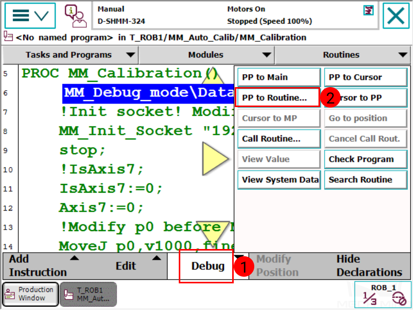
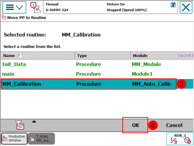
Select MM_Calibration, and then press on OK.
Press the
 key on the teach pendant to run the program until the PP moves to line 17.
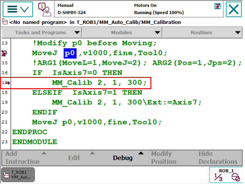
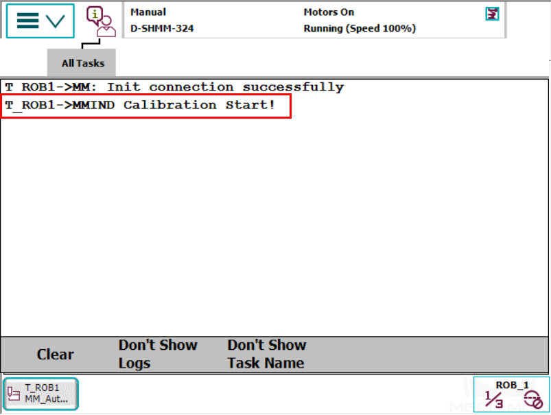
Proceed to the next section when the the following are displayed:
On the teach pendant:
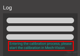
In Mech-Center Log panel:
Start Calibration in Mech-Vision
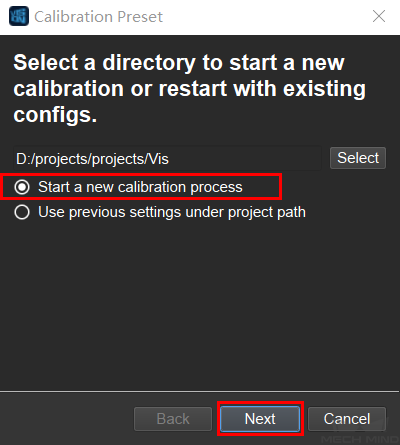
In Mech-Vision, click on Camera Calibration (Standard) in the Toolbar, or select from the Menu Bar.
Follow the instructions in Mech-Vision to complete the following configuration:
Select Start a new calibration process;
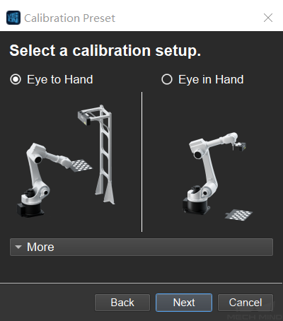
Select the camera mounting method;
Select Multiple random board poses for adding calibration points.
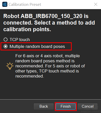
Note
If after selecting the camera mounting method, the window says No robot is connected, the connection between the robot and Mech-Center is not properly established. Please re-run the robot program.
Follow the instructions in Mech-Vision to finish the calibration.
Note
In 5 Add Marker-Images and Poses after you click on Move Robot along Trajectory and Add Board Images, if the robot does not reach the next calibration point within 60 seconds, Mech-Vision will report a timeout error and stop the calibration process. In such case, please select and run MM_Auto_Calib on the teach pendant again, and restart the calibration process in Mech-Vision.