Orderly Arranged Shafts
This section provides guidance on using the Orderly Arranged Shafts project. The overview of the project is as follows.
Workpiece |
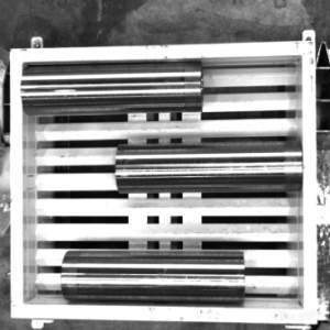
Shafts or bars that are orderly arranged. Multiple layers. Finely processed metal. Highly reflective surface |
Working distance |
1200–3000 mm |
Technical specifications |
Recognition and positioning accuracy: ± 3 mm |
Recognition success rate: more than 99% |
|
Vision cycle time: within 4 s |
Project Description
The Orderly Arranged Shafts project is mainly used for unloading orderly arranged shafts/bars, and it meets the usage requirements of most shaft/bar unloading scenarios.
The following section introduces the Orderly Arranged Shafts project in terms of applicable scenarios and technical specifications.
Applicable Scenarios
This section introduces the applicable scenarios of this project in terms of the workpiece, carrier, gripper, and working distance.
Workpiece
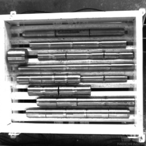
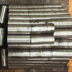
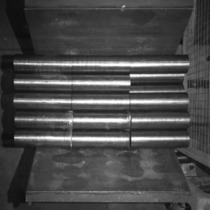
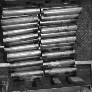
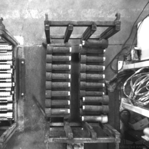
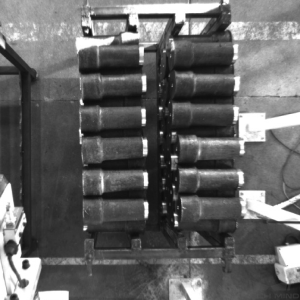
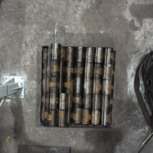
This project is applicable to shafts with the following characteristics.
Workpiece Characteristic |
Application Case |
Example |
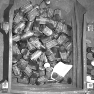
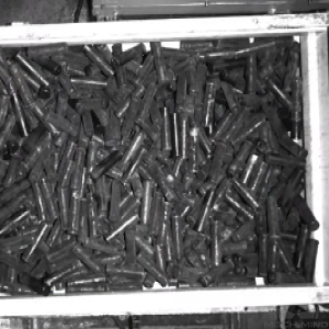
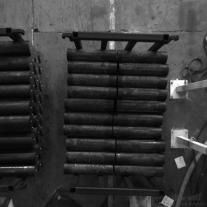
Condition of infeed workpieces |
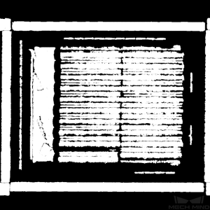
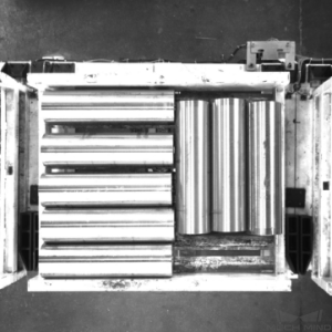
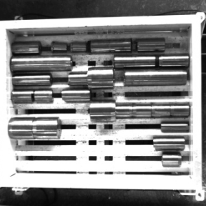
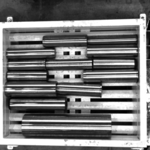
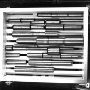
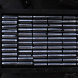
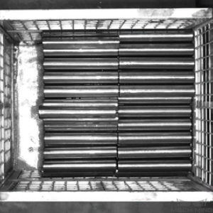
Suitable for common scenarios where shafts/bars are orderly placed |
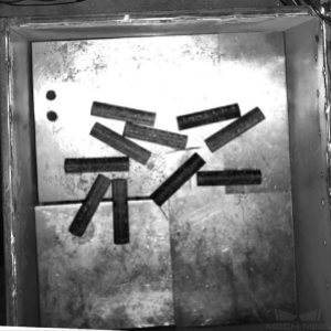
|
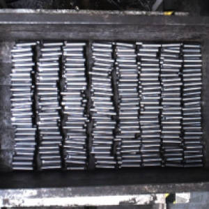
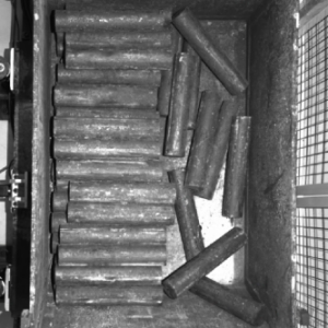
Not suitable for scenarios where shafts/rods are scattered randomly |
|
|
Shape and size |
Suitable for cylindrical objects |
|
Material |
Suitable for metal; rust or small amounts of oil on the surface of the workpiece is acceptable |
|
Reflectivity |
A certain degree of reflection of the workpiece is acceptable |
|
Point cloud quality |
Suitable for scenarios where the missing part of the point cloud that represent significant features is less than 10% of the total scene point cloud |
|

Hint
This project uses a super model of steel bars. For illustrations of shafts/bars that can be identified by the super model, please refer to Appendix .
Carriers
This project is applicable to carriers with the following characteristics.
Carrier Characteristic |
Application Case |
Example |
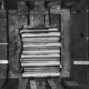
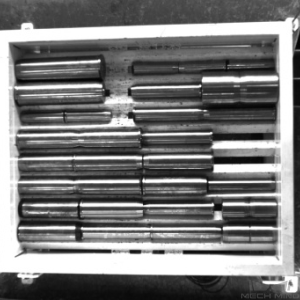
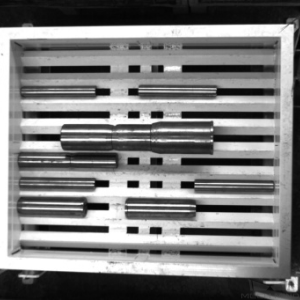
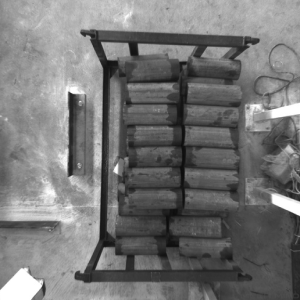
Type of carrier |
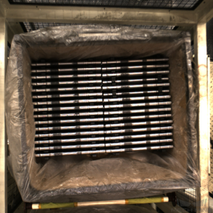
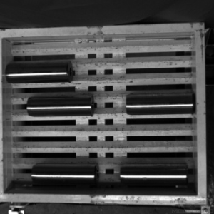
Trays are recommended to use |
|
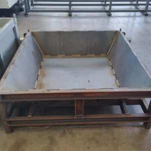
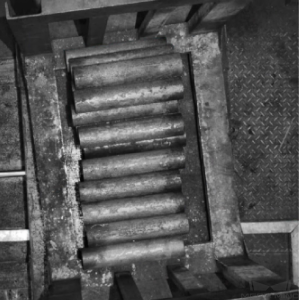
Bins can be used as well; it is recommended to use hopper-shaped bins |
|
|
Not suitable for reflective bin walls, deformed bin walls, and bins with mesh partitions or plastic films |
|
Technical Specifications
The technical specifications of the Orderly Arranged Shafts project are as follows.
Recognition and positioning accuracy: ± 3 mm
Recognition success rate: more than 99%
Vision cycle time: within 4 s
Note
Vision cycle time refers to the amount of time for the project to execute once, from image capturing to outputting vision result.
Project Planning
Layout
Workstation Layout
The layout of the workstation is shown below.
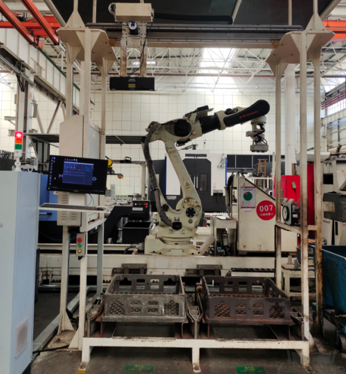
The workflow in the workstation is as follows:
The shafts/bars are moved to the infeed area by the AGV.
The robot sends an image-capturing command to the vision system, and the camera will be triggered to capture the image for recognition. Then the vision system sends the information about the shafts/bars’ positions to the robot.
Guided by the position information sent by the vision system, the robot picks the shaft/bar and places it on a platform for a second positioning.
Repeat the above steps until all the shafts/bars have been loaded.
Hardware of the Vision System
Recommended Specification |
Description |
|
Camera |
LSR L |
Recommended mounting method: Eye-to-Hand (Fixed or sliding); working distance: 1200-3000 mm |
IPC |
Standard model with a GPU (K-Q37MV-Q370) |
Processor: CPU I7-9700 |
RAM: 16G |
||
HDD: 256G SSD |
||
GPU: 1050 TI |
||
WIFI module |
Robot Tool
The robot tool usually used in the Orderly Arranged Shafts project is V-shaped magnetic gripper.
The magnetic gripper is shown in the figure below.
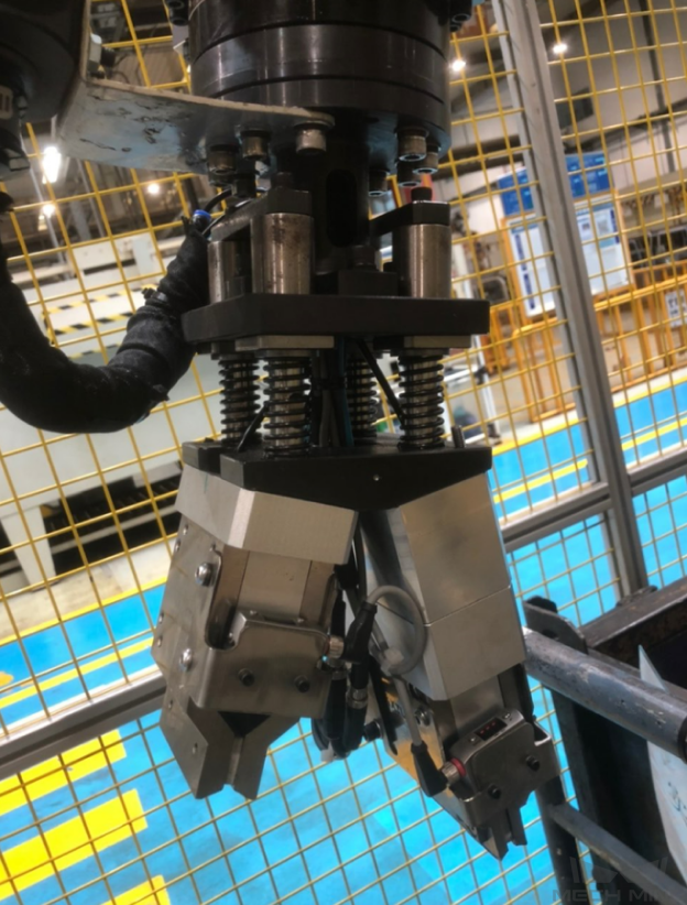
Gripper Description:
Please pay attention to the compatibility of the gripper with shafts of different dimensions. It is recommended to use a robot tool with buffers in the picking direction.
Gripper Advantages:
Using buffers in the picking direction can significantly increase the picking success rate and protect the robot tool at the same time.
Shafts/Rods of different diameters within a certain range can be picked.
Gripper Disadvantages:
When the diameter of the shaft/rod is small, multiple workpieces may be picked at a time.
Vision Solution
Communication Methods
It is recommended to use the Standard Interface for communication.
I. Switch Mech-Vision Recipe |
|||
Robot -> IPC |
Request Command |
Mech-Vision Project ID |
Recipe Number |
103 |
The number on the left of the project name in Mech-Vision’s project list |
1-99 |
|
Example |
103, 1, 2 |
||
IPC -> Robot |
Returned Command |
Status Code |
|
103 |
1107: The recipe is switched successfully 1012: The Mech-Vision recipe number does not exist |
||
Example |
103, 1107 |
||
II. Start Mech-Viz Project |
|||
Robot -> IPC |
Request Command |
Pose Type |
Robot Pose |
201 |
0: No robot pose sent to Mech-Viz 1: Send current joint positions and flange pose of the robot to Mech-Viz 2: Send joint positions of a specific start point to Mech-Viz |
The pose data of the robot in the form of the specified “pose type” |
|
Example |
201, 1, 0, -20.632, -107.812, 0, -92.818, 0.003 |
||
IPC -> Robot |
Returned Command |
Status Code |
|
201 |
2103: The execution is successful 2008: An error occurs when the project is running …… |
||
Example |
201, 2103 |
||
III. Select Mech-Viz Branch |
|||
Robot -> IPC |
Request Command |
ID of the Branch Step |
Number of the Exit Port |
203 |
This parameter should be a positive integer. It is used to specify the ID of the branch Step along which the project will proceed. |
This parameter should be a positive integer. It is used to select the exit port of the Step that the project will take. |
|
Example |
203, 1, 1 |
||
IPC -> Robot |
Returned Command |
Status Code |
|
203 |
2105: The execution is successful 2018: The number of the exit port is invalid …… |
||
Example |
203, 2105 |
||
IV. Get Planned Path (Recommended) |
||||||
Robot -> IPC |
Request Command |
Type of Waypoint |
||||
205 |
1: Joint positions 2: TCP |
|||||
Example |
205, 1 |
|||||
IPC -> Robot |
Returned Command |
Status Code |
Whether All Waypoints Have Been Sent |
Number of Waypoints |
Position of “Vision Move” |
Waypoint |
205 |
2100: The execution is successful 2007: Failed to plan a path …… |
0: NOT all waypoints have been sent 1: All waypoints have been sent |
Default range: 0-20 If there are more than 20 waypoints in the path, execute this command multiple times. |
The position of the first Vision Move waypoint in the path |
Object pose Label Speed |
|
Example |
205, 2100, 1, 2, 2, 8.307, 15.163, -142.177, -2.775, -31.440, -96.949, 0, 64 |
|||||
V. Get Vision Targets (For applications that use Mech-Vision but not Mech-Viz; not recommended) |
||||||
Robot -> IPC |
Request Command |
Mech-Vision Project ID |
||||
102 |
The number on the left of the project name in Mech-Vision’s project list |
|||||
Example |
102, 1 |
|||||
IPC -> Robot |
Returned Command |
Status Code |
Whether All Vision Targets Have Been Sent |
Number of TCP |
Reserved Fields |
Vision Target |
102 |
1100: The execution is successful 1102: No vision points …… |
0: NOT all vision points have been sent 1: All vision points have been sent |
Default range: 0-20 |
This field is not used. The default value is 0. |
Object pose Label Speed |
|
Example |
102, 1100, 1, 1, 0, 95.780, 644.567, 401.101, 91.120, -171.130, 180.0, 0, 0 |
|||||
For details, refer to the Standard Interface Communication section.
Project Description
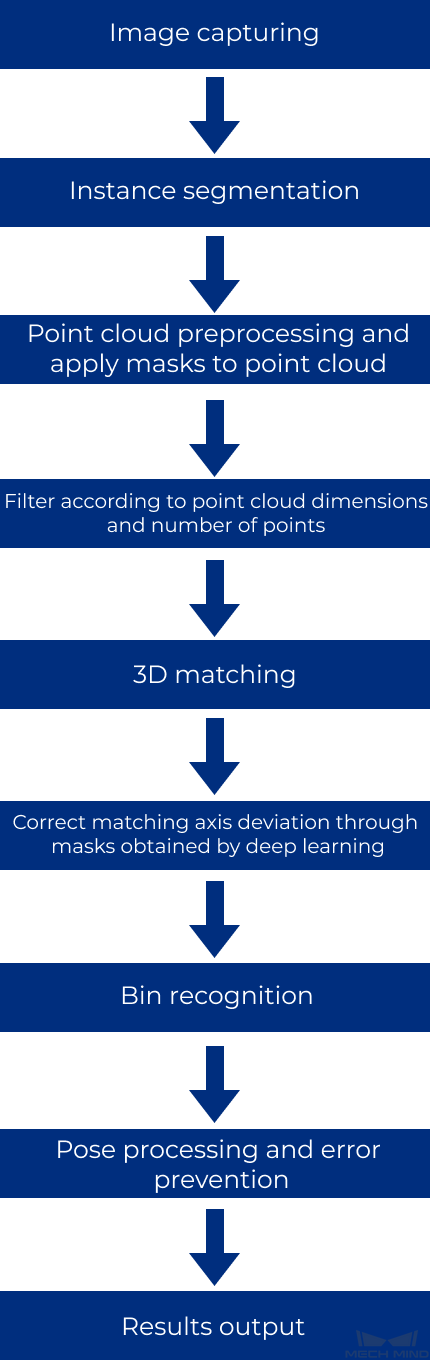
Image capturing: Obtain the color image and depth map of the shaft.
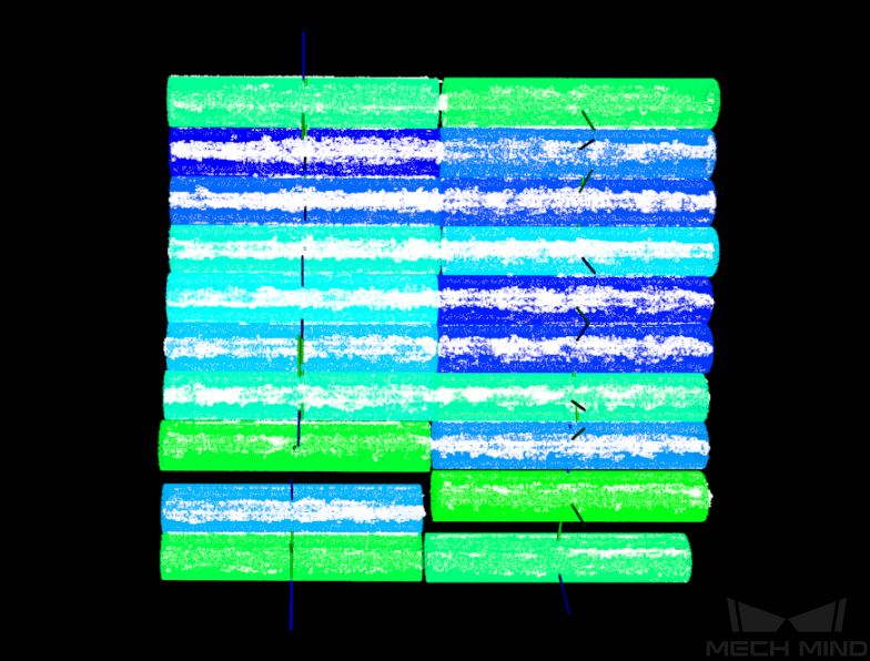
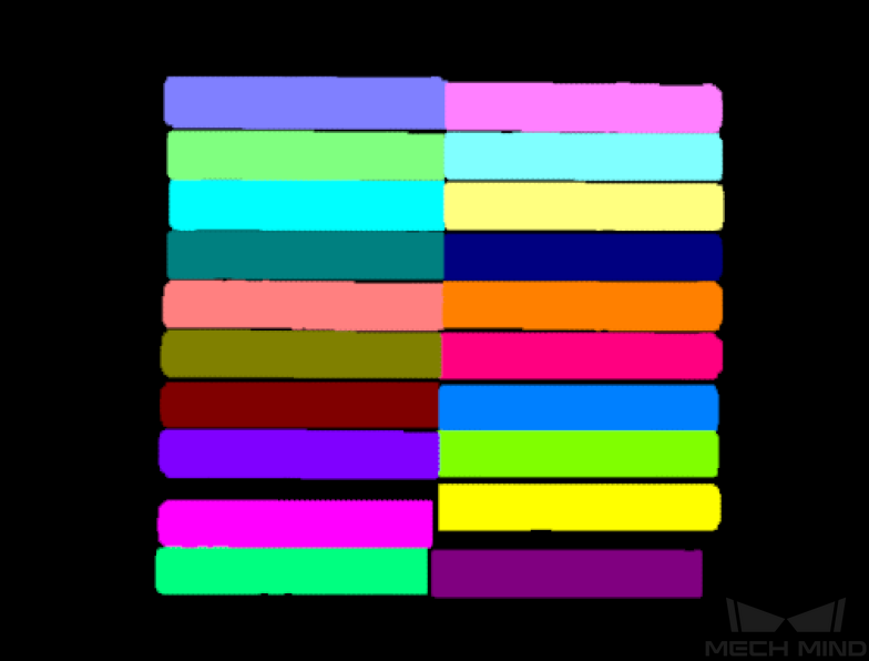
Instance segmentation: Identify shafts by using deep learning super models.
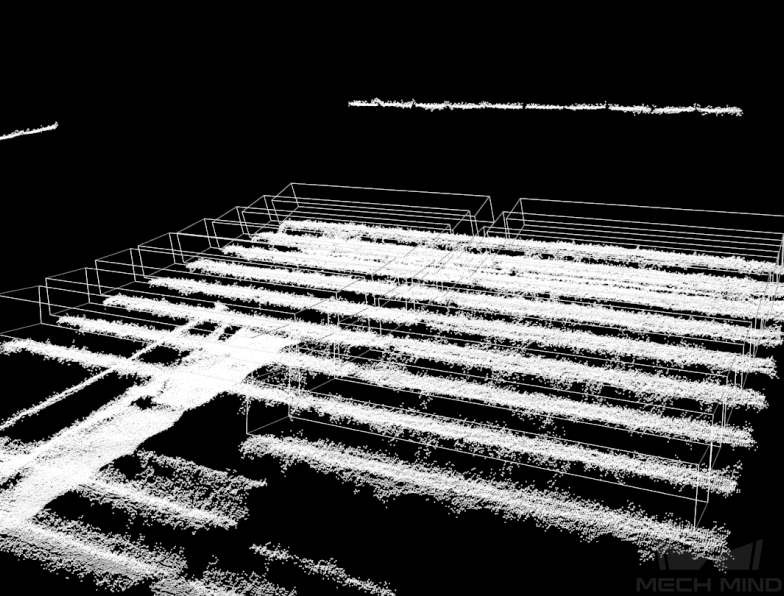
Point cloud preprocessing and apply masks to point cloud: Pre-process the original point cloud of the shafts and apply masks to point clouds.
Filter according to point cloud dimensions and number of points: Filter out unqualified point clouds of the shafts according to the set rules.
3D matching: The point cloud model generated from the STL model will be used to match with the actual point cloud in the scene to obtain more accurate pick points.
Correct matching axis deviation through masks obtained by deep learning: Correct matching deviation from the actual axis direction by deep learning.
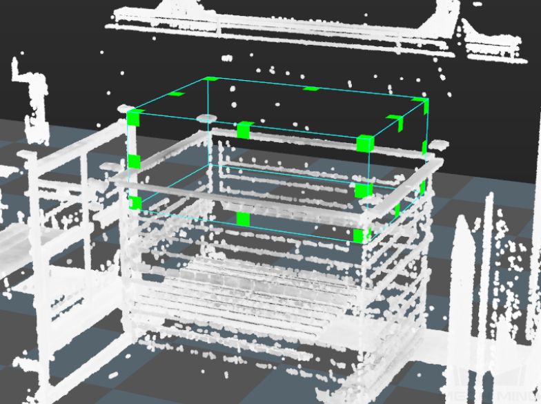
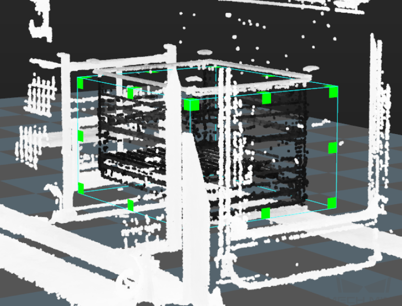
Bin recognition: Calculate the center pose based on the bin’s top edge, and filter out unqualified bin center poses according to the ROI and orientation of the bin.
Pose processing and error prevention: Transform and sort the pick points of shafts and filter out the unqualified pick points according to the set rules.
Results output: Send the results of the current project to the backend service.
Generate Point Cloud Model and Add Pick Point
Point cloud models are generally generated from the STL model, with the pick point set in the middle of the shaft’s axis.
Project Difficulties
There may be deviations from the direction of the shaft/rod’s axis during the matching and recognition process.
The point cloud quality of the smooth shafts/rods is relatively poor.
A high recognition and positioning accuracy is required when the robot tool is less flexible when moving.
The workpieces on the top layer may be missed when deep learning is used for recognition.
Project Advantages
The project can be used to locate the bin and recognize the workpiece.
There are buffers in the picking direction, which significantly increases the picking success rate.
This project has effective error-proofing Steps to ensure the stability of the project.
The parameters of recognition Steps show a high recognition stability, which has been verified by repeated tests.
Project Deployment
Cautions
Compatibility of tools for different workpiece sizes: When there are workpieces of different specifications in one work station, and there is only one robot tool, please consider whether the tool can be used to pick workpieces of all different specifications. Situations where multiple workpieces are picked at one time or the robot tool is not suitable for picking a certain type of workpiece should be avoided.
The picking tolerance should be as large as possible: The point cloud quality of reflective workpieces is relatively poor, and therefore the picking tolerance of the selected robot tool should be as much as possible for a higher recognition and positioning accuracy.
Placement margin: The recommended lengthwise margin for placement is ±30mm or more if it is possible and ±10mm where there are restrictions.
Deep learning model: The deep learning super model is used in the project. However, the data used for training is limited. If the deep learning is not effective in the project, more data should be collected and the super model should be iterated.
Suggestions for Parameter Adjustment
Instance Segmentation
Image Brightness and Color Balancer : When the 2D image is too dark, the brightness can be increased by adjusting the gamma parameter in this Step. In the on-site testing process, the lighting conditions and camera parameters should be adjusted to ensure that the 2D image is of the right brightness.
Deep Learning Model Package Inference (Mech-DLK 2.2.0+) : Identifying shafts by using deep learning super models of shafts. If there is any problem with the deep learning recognition, the image data should be collected to iterate the model and an appropriate ROI should be set.
Point Cloud Preprocessing and Apply Masks to Point Cloud
Extract 3D Points in 3D ROI : An appropriate ROI should be set.
Point Cloud Preprocessing : The noise points should be removed and the corresponding point clouds in the mask should be extracted.

Filter According to Point Cloud Dimensions and Number of Points
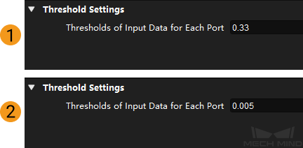
Dichotomize Values by Threshold : The minimum size of the long (figure 1 below) and short (figure 2 below) edges of the workpiece should be set. When the size of the long or short edges of the workpiece is smaller than the minimum size, the point cloud and mask of the corresponding workpiece should be filtered out.
Validate Point Clouds : Set the Min Number of Points and Max Number of Points to filter out point clouds and corresponding masks where the number of points does not meet the rules.
3D Matching
3D Fine Matching : The confidence threshold should be set to 0 and cannot be changed. In the subsequent Steps, the workpiece poses with lower matching scores can be filtered out, and the output workpiece poses in the matching process can correspond with the masks generated from instance segmentation. Relevant parameters should also be adjusted to reduce the matching deviation.
Correct Matching Axis Deviation Through Masks Obtained By Deep Learning
Dichotomize Values by Threshold : Set the Thresholds of Input Data for Each Port as a matching score threshold to filter out workpiece point clouds and poses with low matching scores.
Point Axes of Poses to Given Direction : Set the appropriate Reference Direction .
Convert 2D Points to 3D Points : The generated point cloud should correspond to the original workpiece.
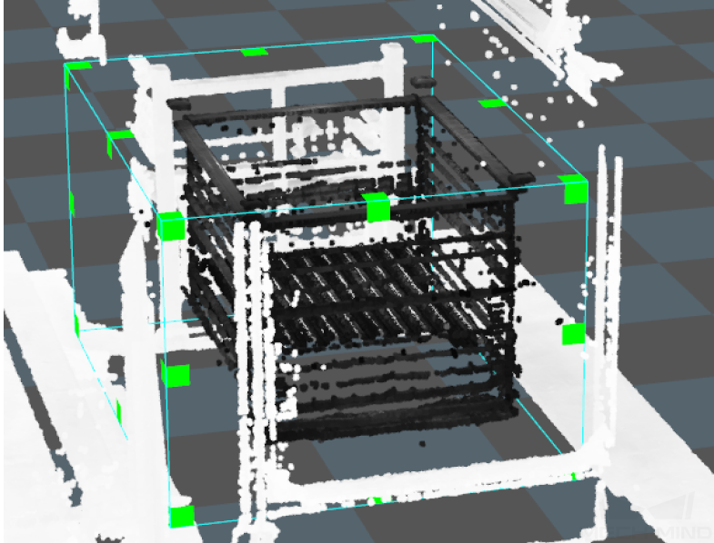
Bin Recognition
This project obtains the pose of the bin by calculating the planar poses, you can adjust the Steps to recognize the bin according to the actual situation. This Procedure is used to calculate the center pose of the bin’s top edge and to set the dimensions, ROI, and can also be used to perform orientation error prevention.
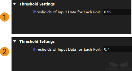
Dichotomize Values by Threshold : The minimum dimensions of the long side (figure 1 below) and the short side (figure 2 below) of the bin should be set.
Filter poses according to ROI and orientation
Validate Poses by Included Angles to Reference Direction : The Max Angle Difference should be set.
Validate Existence of Poses in 3D ROI : The 3D ROI should be set.
Pose Processing and Error Prevention
Translate Poses along Given Direction (position at a certain distance above the center pose of the bin): The Translation Distance should be set as the offset length of the reference point.
Translate Poses along Given Direction (The bin center pose used to update the bin position in Mech-Viz): The Translation Distance should be set as an offset length of the bin center from the top surface of the bin.
Get Highest-Layer Poses : The Layer Height should be set.
Sort 3D Poses : The Sort Method should be set.
Easy Create Number List : You should set the Number List as the diameter of the shaft/rod’s cross-section.
Extract 3D Points in Cuboid (The “Filtering out the pinned workpiece pose” Procedure): The Box Dimensions Settings should be set to extract the point cloud above the workpiece instead of the workpiece itself.
Dichotomize Values by Threshold : The Thresholds of Input Data for Each Port should be set as a threshold to filter the point clouds. Workpieces with a value higher than the threshold will be considered to be overlapped and their point clouds will be filtered out.
Filter poses according to ROI and orientation
Validate Poses by Included Angles to Reference Direction : The Max Angle Difference should be set.
Validate Existence of Poses in 3D ROI : The 3D ROI should be set.
Common Problems and Solutions
Deep Learning Recognition Error
When the recognition of the shaft/bar via deep learning fails, follow the steps below to try and fix the problem.
Retrain the deep learning model, and the data is required to be re-collected.
Delete the “Correct matching axis deviation through masks obtained by deep learning” Procedure.
Appendix
The following section shows more scenarios where the deep learning super model can be used.
Horizontal placement
Reflective
When there is a degree of reflection on the surface of the shafts, illustrations of shafts that can be recognized by the super model are shown in the table below.
Reflective |
|||
|
|
|
|
|
|
|
|
|
|
|
|
|
|
|
|
|
|
|
|

Non-reflective
When the shafts are not reflective, illustrations of shafts that can be recognized by the super model are shown in the table below.
Non-reflective |
|||
|
|
|
|
|
|
|
|
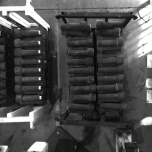
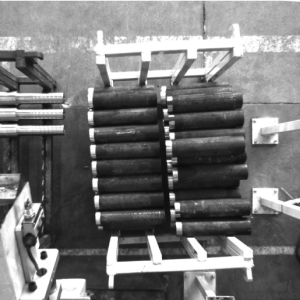
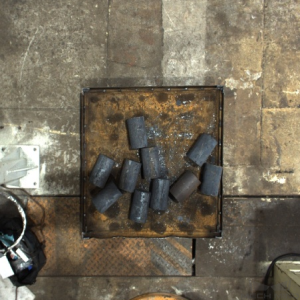
Vertical Placement
When the workpiece is placed vertically, an illustration of the shaft that can be recognized by the super model is shown in the table below.
Vertical placement |
|
Scattered Incoming Materials
When the shafts are scattered randomly, illustrations of shafts that can be recognized by the super model are shown in the table below.
Scattered incoming materials |
||
|
|
|
|
|
|
|
|
|