Orderly Arranged Gearbox Housing
This section provides guidance on using the Orderly Arranged Gearbox Housing project. The overview of the project is as follows.
Workpiece |
Gearbox housings of the same specifications, orderly arranged |
Working distance |
1000–1500 mm |
Technical specifications |
Recognition and positioning accuracy: ±1 mm |
Recognition success rate: more than 99% |
|
Vision cycle time: less than 4 s |
Project Description
The following section introduces the Orderly Arranged Gearbox Housing project in terms of applicable scenarios and technical specifications.
Applicable Scenarios
This section introduces the applicable scenarios of this project in terms of the workpiece, carriers, robot tools and working distance.
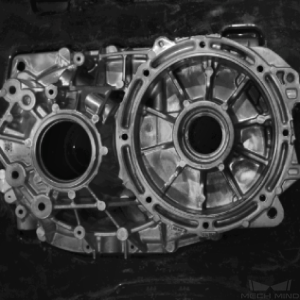
Workpiece
This project is applicable to shafts with the following characteristics.
Workpiece Characteristic |
Application Case |
Example |
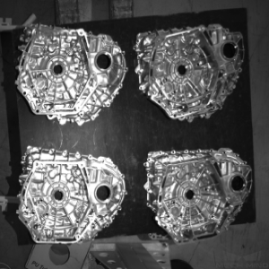
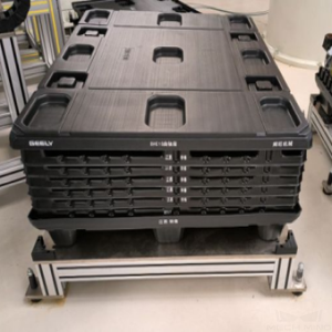
Condition of infeed workpieces |
Suitable for gearbox housings that are orderly-arranged |
|
Not suitable for gearbox housings that are stacked randomly or closely to each other |
|
|
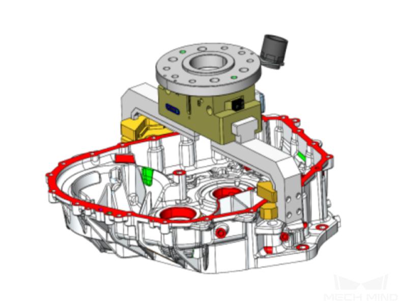
Shape and size |
Suitable for special-shaped or rectangular gearbox housings |
|
Material |
Rough machined metal parts such as gray cast iron and aluminum alloy |
|
Reflectivity |
A certain degree of reflection on the workpiece surface is allowed |
|
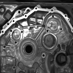
Point cloud quality |
The point cloud of the gearbox housing’s upper surface must not have significant missing parts |
|
Stacking |
Suitable for single layer, or multiple layers orderly stacked |
|
Not suitable for scenarios where gearbox housings are embedded in partitions with holes of a similar shape as the gearbox housing (which may hinder point cloud clustering) |
|

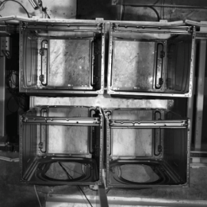


Carriers
This project is applicable to carriers with the following characteristics.
Characteristic of the Cylinder Head |
Applicable/Not Applicable Cases |
Example |
Type of carrier |
Trays are recommended |
|
Deep bins can also be used. |
|
|
Condition of bin walls |
Applicable to metal bin walls and metal mesh bin walls |
|
Not applicable to reflective bin walls and bins with plastic films that may cause interference |
||
Deformation of bin walls |
If dynamic bin detection is not performed, the deformation of bin walls is allowed |
|
Condition of partitions |
Applicable to plastic partitions, transparent partitions, and partitions with oil stains or indentations |
|
Not applicable to deformed partitions |
||
Point cloud quality |
Applicable to carriers with partitions whose point cloud can well represent its features |

Lighting Conditions
This solution is applicable to the following lighting conditions.
Lighting Condition |
Application Case |
Environment Light |
No direct sunlight on the surface of the workpiece |
Artificial Light |
Extra artificial light not required |
Technical Specifications
The technical specifications of the Orderly Arranged Gearbox Housing project are as follows.
Recognition and positioning accuracy: ±1 mm
Recognition success rate: more than 99%
Vision cycle time: less than 4 s
Note
Vision cycle time refers to the amount of time for the project to execute once, from image capturing to outputting vision result.
Project Planning
Layout
Workstation Layout
The layout of the workstation is shown below.

The workflow in the workstation is as follows:
After the gearbox housings are moved to the infeed area, the robot carries the camera on it to a pre-defined position to capture images for recognition.
Guided by the vision system, the robot picks the gearbox housing on the tray and places it to a specified region.
The steps above will be repeated until all gearbox housings on the same layer have been picked. Then the robot will pick the partition and place it to a specified region.
The steps above will be repeated until all gearbox housings and partitions on the infeed pallet have been picked.
Hardware of the Vision System
Recommended Specification |
Description |
|
Camera |
Pro S Enhanced |
Recommended mounting method: eye-in-hand; working distance: 1000-1500 mm |
LSR L |
Recommended mounting method: eye-to-hand; working distance: 2000-2500 mm |
|
IPC |
Standard model without a GPU (Q6WMV-B-1A1) |
Processor: CPU I5-12400 |
RAM: 16G DDR4 |
||
HDD: 256G SSD |
||
Power supply: DC24V 7.5A |
||
Operating system: Windows 10 21H1 |
||
WIFI module |
Robot Tool
Description of the robot tool:
There are two types of common tools used in this project: clamp gripper, and locating pin clamp gripper. Usually, clamp locating pin clamp grippers are recommended in this project.
Notes for Tool Design:
If the gripper consists of a pin or locating pin, the clearance between the locating pins and the pin holes should be moderate, and the workpiece should not be gripped by the locating pins alone. Instead, a more stable fixture should be used for picking at the same time.
The strength of the locating pin should be high, and the chamfer of the locating pins should be increased to facilitate guiding positioning.
Collision with the neighboring workpieces should be avoided when the gripper picks or places a workpiece.
Clamp Gripper
The clamp gripper is shown in the figure below.
Gripper Description:
The clamp gripper is controlled by a cylinder or servo motor, and the gripper grasps the workpiece from the concave and convex parts of the workpiece. This type of gripper is applicable to projects that do not require high accuracy in placement position.
Gripper Advantages:
The recognition and positioning accuracy is usually within ±2 mm. A picking deviation within a certain range is allowed, and the picking stability is good.
The TCP setting on the robot end is simple and the pick point can be added by teaching conveniently.
Gripper Disadvantages:
Using this type of gripper requires some distance between workpieces, or else collisions may occur.
The picking and placing accuracy of this gripper is not high enough, and therefore it is not suitable for high-precision positioning projects.
Locating Pin Clamp Gripper
The locating pin clamp gripper is shown in the figure below.
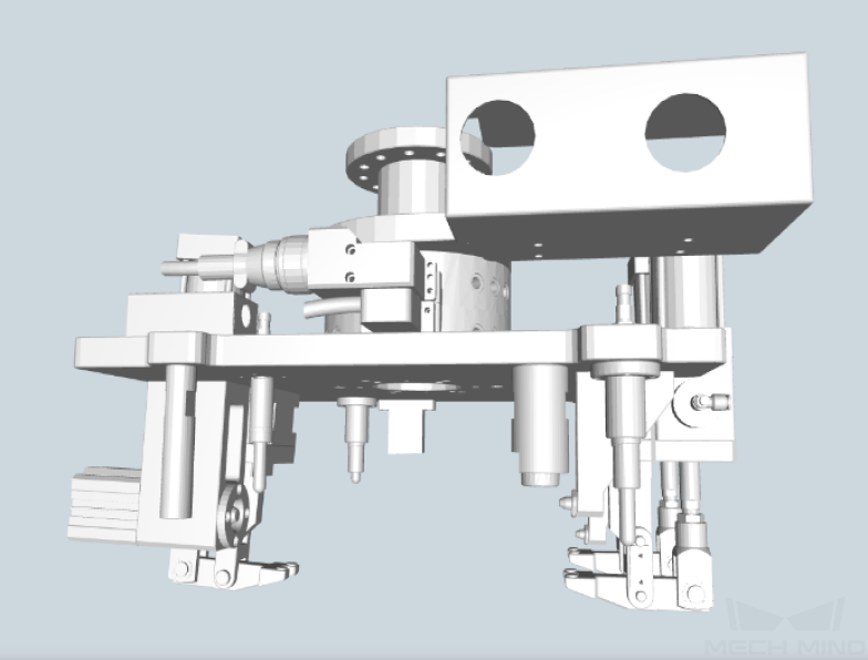
Gripper Description:
This gripper grasps the workpiece by inserting the locating pins into the corresponding pin holes of the workpiece and grasping the entire workpiece. This type of gripper is applicable to projects that require high accuracy in placement position.
Gripper Advantages:
The picking and positioning accuracy are high.
Gripper Disadvantages:
The teaching process on the robot end is more complicated.
Vision Solutions
Communication Method
It is recommended to use the Standard Interface for communication.
I. Switch Mech-Vision Recipe |
|||
Robot -> IPC |
Request Command |
Mech-Vision Project ID |
Recipe Number |
103 |
The number on the left of the project name in Mech-Vision’s project list |
1-99 |
|
Example |
103, 1, 2 |
||
IPC -> Robot |
Returned Command |
Status Code |
|
103 |
1107: The recipe is switched successfully 1012: The Mech-Vision recipe number does not exist |
||
Example |
103, 1107 |
||
II. Start Mech-Viz Project |
|||
Robot -> IPC |
Request Command |
Pose Type |
Robot Pose |
201 |
0: No robot pose sent to Mech-Viz 1: Send current joint positions and flange pose of the robot to Mech-Viz 2: Send joint positions of a specific start point to Mech-Viz |
The pose data of the robot in the form of the specified “pose type” |
|
Example |
201, 1, 0, -20.632, -107.812, 0, -92.818, 0.003 |
||
IPC -> Robot |
Returned Command |
Status Code |
|
201 |
2103: The execution is successful 2008: An error occurs when the project is running …… |
||
Example |
201, 2103 |
||
III. Select Mech-Viz Branch |
|||
Robot -> IPC |
Request Command |
ID of the Branch Step |
Number of the Exit Port |
203 |
This parameter should be a positive integer. It is used to specify the ID of the branch Step along which the project will proceed. |
This parameter should be a positive integer. It is used to select the exit port of the Step that the project will take. |
|
Example |
203, 1, 1 |
||
IPC -> Robot |
Returned Command |
Status Code |
|
203 |
2105: The execution is successful 2018: The number of the exit port is invalid …… |
||
Example |
203, 2105 |
||
IV. Get Planned Path (Recommended) |
||||||
Robot -> IPC |
Request Command |
Type of Waypoint |
||||
205 |
1: Joint positions 2: TCP |
|||||
Example |
205, 1 |
|||||
IPC -> Robot |
Returned Command |
Status Code |
Whether All Waypoints Have Been Sent |
Number of Waypoints |
Position of “Vision Move” |
Waypoint |
205 |
2100: The execution is successful 2007: Failed to plan a path …… |
0: NOT all waypoints have been sent 1: All waypoints have been sent |
Default range: 0-20 If there are more than 20 waypoints in the path, execute this command multiple times. |
The position of the first Vision Move waypoint in the path |
Object pose Label Speed |
|
Example |
205, 2100, 1, 2, 2, 8.307, 15.163, -142.177, -2.775, -31.440, -96.949, 0, 64 |
|||||
V. Get Vision Targets (For applications that use Mech-Vision but not Mech-Viz; not recommended) |
||||||
Robot -> IPC |
Request Command |
Mech-Vision Project ID |
||||
102 |
The number on the left of the project name in Mech-Vision’s project list |
|||||
Example |
102, 1 |
|||||
IPC -> Robot |
Returned Command |
Status Code |
Whether All Vision Targets Have Been Sent |
Number of TCP |
Reserved Fields |
Vision Target |
102 |
1100: The execution is successful 1102: No vision points …… |
0: NOT all vision points have been sent 1: All vision points have been sent |
Default range: 0-20 |
This field is not used. The default value is 0. |
Object pose Label Speed |
|
Example |
102, 1100, 1, 1, 0, 95.780, 644.567, 401.101, 91.120, -171.130, 180.0, 0, 0 |
|||||
For details, refer to the Standard Interface Communication section.
If you want to use the Adapter communication method, a customized program should be written.
Robot -> IPC |
Request Command |
Mech-Vision Project ID |
Workpiece Model |
|
“P”: Request to capture images |
1-9 |
1-99 |
||
Example |
P, 1, 2 |
|||
Description |
Capture the image, project ID 1, workpiece model 2 |
|||
IPC -> Robot |
Status Code |
Workpiece Model |
Front and Back of the Workpiece |
Pick Point |
0: The recognition is successful 1: No workpiece 2: Recognition failure |
1-99 |
1: Front side 2: Back side |
X,Y,Z,A,B,C |
|
Example |
102, 1100, 1, 1, 0, 95.780, 644.567, 401.101, 91.120, -171.130, 180.0, 0, 0 |
|||
Description |
The photo was taken successfully, workpiece model 1, back side, pick point 1.574 , -0.443 , -1.122 , 43.12 , -24.25 , 179.66 |
|||
Project Description
This project adopts the method of surface matching, and the models at two different angles are automatically selected for matching according to the different angles of the incoming gearbox housings.
The general workflow of this project is shown in the diagram below.
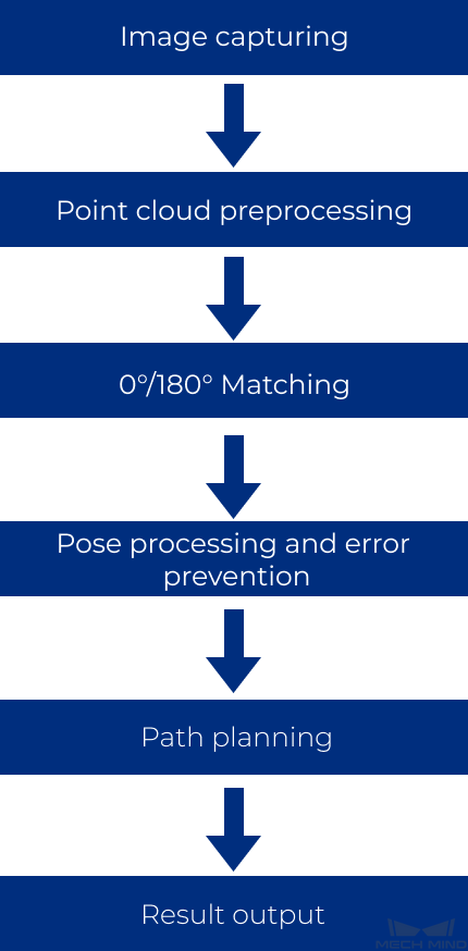
Image capturing: Obtain the color image and depth map of the gearbox housings.
Point cloud preprocessing: Preprocess the original point cloud of the gearbox housings.
0°/180° Matching: If the incoming gearbox housings are at the same angle, you can choose Match0 for Match Mode and use a single point cloud model to match with the original point cloud for obtaining more accurate picking poses.
Pose processing and error prevention: Transform and sort the picking poses, and check the validity of the poses.
Path palnning: Plan a path for the robot to pick.
Result output: Send the results of the current project to the backend service.
Generate Point Cloud Model and Add Pick Point
The project uses surface point cloud models. As incoming gearbox housings are at different angles, two models at different angles can be used for matching and outputting poses to improve the recognition and positioning accuracy.
Since the robot tool is complicated, it is not easy to add pick points accurately by dragging. Please adjust the robot pose manually through the teach pendant and obtain the pick point from the robot .
Project Advantages
The point cloud pre-processing in this project is stable.
This project recognizes gearbox housings by surface matching with high recognition stability, which has been verified with different similar gearbox housings.
This project is applicable to infeed workpieces that are placed in various orientations.
This project has effective error-proofing Steps to ensure the quality and correctness of the output point cloud and poses.
Project Difficulties
The requirements on the arrangement of incoming materials are high: the incoming materials should be orderly arranged.
The surface of the workpiece needs to be not reflective, and the quality of the point cloud needs to be good.
The project must be able to recognize both the front and back sides of the gearbox housing.
Project Deployment
Cautions
The requirements on the arrangement of incoming materials are high: the incoming materials should be orderly arranged.
The project requires the surface of the workpiece to be not reflective and the quality of the point cloud to be good.
Suggestions for Parameter Adjustment
Point Cloud Preprocessing
Down-Sample Point Cloud : It is necessary to reduce the number of points in the scene point cloud to an appropriate range (less than 100,000 recommended) by setting a Sampling Interval, so as to improve the subsequent processing speed.
Point Filter : Generally, the NormalsFilter method is used to filter out noises, such as the noises of the part between the upper surface of the workpiece and the lower structure, and obtain a complete point cloud of the upper surface. Ensure that the point cloud of the workpiece is complete.

Obtain the highest layer point cloud under the robot frame
Transform Point Clouds : Due to the pose of the camera, the highest layer point cloud in the camera reference frame may be inaccurate. Therefore, it is necessary to select CameraToRobot for Transformation Type to transform the point cloud to the robot reference frame , and then obtain the highest layer point cloud.
Get Highest Layer Clouds : It is necessary to obtain an accurate highest layer point cloud, and try not to include point clouds other than the workpiece point cloud to be matched.

0°/180° Matching
“0°/180°” does not refer to the angles literally. If the incoming workpieces are all at the same angle , it is considered to be 0°; if the incoming workpieces are at two angles, two point cloud models (0°/180°) must be generated for matching the workpieces at different angles respectively.
In this Procedure, select Match0 in the drop-down menu of Match Mode to match using only the 0° model; select Match0And180 to match using both the 0° and 180° models. The pick points on the two models should be added by adjusting the robot pose manually through the teach pendant and obtaining the pick point from the robot.
3D Coarse Matching V2: It is recommended to select Surface Matching for Matching Mode , and set Expected Point Count of Sampled Model to 1000. This value can be adjusted according to the actual situation on site, provided that the matching accuracy is guaranteed.
3D Fine Matching: It is recommended to select Origin (use the normal of the input point cloud) for Point Orientation Calc Mode , set Sampling Interval as 1.000 mm , set Confidence Threshold to 0.700 and above, and set Search Radius to 5.000 mm and below. After setting the above parameters, make sure that the workpiece with complete point cloud can be accurately matched without misalignment.
Pose Processing
Adjust Poses: The pose of the workpiece in the camera reference frame must be transformed to the robot reference frame by selecting Camera_To_Robot for Transform Type. Select Sort_By_Custom_Direction or SORT_BY_POSITION_XYZ (the Specific Value of Position is Z) for Sorting Type.
Validate Poses by Included Angles to Reference Direction: Select X for Pose’s Selected Axis, set the X value of Reference Direction to -1.0000 or 1.0000 , and set Maximum Angle Difference to 45°. These settings are used to filter the 0° or 180° workpieces based on the angle between the specified axis and the reference direction.
Path Planning
In the Path Planning Step, click Open path planning tool to open the tool.
The general workflow of the planned path is: Home position -> Above-bin fixed waypoint -> Above-workobject approaching waypoint -> Vision point -> Above-workobject departure waypoint -> Above-bin fixed waypoint -> Home position. Before configuring the workflow, you should set the corresponding robot tool and set a home position according to the on-site situation. Then you can adjust the above-bin fixed waypoint and the above-workobject approaching waypoint and add scene objects and configure the collision detection settings.
In the Step Parameters panel of Path Planning, select the configured workflow in the drop-down list of Workflow Configuration.
Common Problems and Solutions
No Output from 3D Fine Matching
Check whether the point cloud output by the “Point Cloud Preprocessing” Procedure is normal.
If the point cloud output by the “Point Cloud Preprocessing” Procedure is abnormal, check whether the output result and the original depth map of the Steps “Point Cloud Clustering” and “Get Highest Layer Clouds” are normal.
If the point cloud output by the “Point Cloud Preprocessing” Procedure is normal, check the visual output of the “3D Coarse Matching V2” Step. If the visual output of the “3D Coarse Matching V2” Step is abnormal, check whether the Expected Point Count of Sampled Model and the Referring Point Sampling Step are set properly.
If the output result of the “3D Coarse Matching V2” Step is normal but the “3D Fine Matching” Step has no output, check whether the parameters Standard Deviation, Confidence Threshold, and Search Radius are set properly.
Deviations when Picking Workpieces
If deviations are present when the robot picks the workpiece, the following checks can be done:
Analyze whether the deviations follow a certain pattern or not;
Check if deviations and obvious misalignments are present in the current matching result;
Analyze the recognition accuracy of individual workpieces;
Check the accuracy of the camera extrinsic parameters.
If no problems are found in the above checks, check the robot accuracy and TCP accuracy again.