Track Shoes
This section provides guidance on using the Track Shoes project. The overview of the project is as follows.
Workpiece |
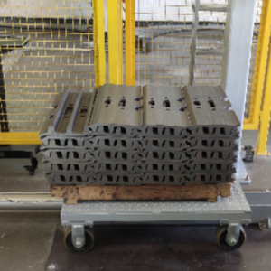
The track shoes with front and back sides alternately facing up, no obvious reflection, single object type |
Carrier |
Tray |
Working distance |
1200–3000 mm |
Technical specifications |
Recognition and positioning accuracy: ± 5 mm |
Recognition success rate: more than 99.9% |
|
Vision cycle time: within 6 s |
Note
The front side of the track shoe described in this section refers to the side with the metal bar facing up, while the other side without the metal bar is the back side.
Project Description
The following section introduces the Track Shoes project in terms of applicable scenarios and technical specifications.
Applicable Scenarios
This section introduces the applicable scenarios of this project in terms of the workpiece and working distance.
Workpiece
This project is applicable to track shoes with the following characteristics.
Workpiece Characteristic |
Application Case |
Example |
Condition of the infeed workpieces |
Suitable for workpieces that are orderly arranged |
|
Not suitable for workpieces that are scattered randomly |
||
Shape and size |
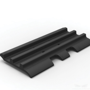
Suitable for flat track shoes with metal bar |
|
Material |
Alloy steel |
|
Reflectivity |
Suitable for workpieces that are not highly reflective |
|
Point cloud quality |
Suitable for scenarios where the missing part of the point cloud that represent significant features is less than 5% of the total scene point cloud |
|
Not suitable for obviously incomplete point clouds |
|


Carriers
This project is applicable to carriers with the following characteristics.
Characteristic of the Carrier |
Applicable Cases |
Example |
Type of carrier |
Tray |
|

Technical Specifications
The technical specifications of the track shoes unloading project are as follows.
Recognition and positioning accuracy: ± 5 mm
Recognition success rate: more than 99.9%
Vision cycle time: within 6 s
Note
Vision cycle time refers to the amount of time for the project to execute once, from image capturing to outputting vision result.
Project Planning
Layout
Workstation Layout
The layout of the workstation is shown below.

The workflow in the workstation is as follows:
The track shoe is moved to the infeed area by a manual forklift.
The robot sends an image-capturing command to the vision system, and the camera will be triggered to capture the image for recognition. Then the vision system sends the position information of the track shoe to the robot.
Guided by the position information sent by the vision system, the robot picks the track shoe and places it on a platform for a second positioning.
Repeat the above steps until all track shoes have been loaded.
Hardware of the Vision System
Recommended Specification |
Description |
|
Camera |
LSR L |
Recommended mounting method: Eye-to-Hand; working distance: 1200-3000 mm |
IPC |
Standard model with a GPU (K-Q37MV-Q370) |
Processor: CPU I7-9700 |
RAM: 16G |
||
HDD: 256G SSD |
||
GPU: 1050 TI |
||
WIFI module |
Robot Tool
The robot tool usually used in the Track Shoes project is shown in the figure below.

Gripper Description:
A magnetic gripper is usually used in the Track Shoes project. Using a gripper without any buffer requires the accuracy of the recognized pose to be very high. While using a magnetic gripper with buffers allows some picking deviation in the picking direction, but also allows some small recognition deviation in the workpiece recognition process. Increasing the strength of the electromagnet can also lead to a more relaxed requirement on recognition accuracy.
Gripper Advantages:
Using a gripper with buffers in the picking direction can significantly increase the picking success rate.
Vision Solutions
Communication Method
It is recommended to use the Standard Interface for communication.
I. Switch Mech-Vision Recipe |
|||
Robot -> IPC |
Request Command |
Mech-Vision Project ID |
Recipe Number |
103 |
The number on the left of the project name in Mech-Vision’s project list |
1-99 |
|
Example |
103, 1, 2 |
||
IPC -> Robot |
Returned Command |
Status Code |
|
103 |
1107: The recipe is switched successfully 1012: The Mech-Vision recipe number does not exist |
||
Example |
103, 1107 |
||
II. Start Mech-Viz Project |
|||
Robot -> IPC |
Request Command |
Pose Type |
Robot Pose |
201 |
0: No robot pose sent to Mech-Viz 1: Send current joint positions and flange pose of the robot to Mech-Viz 2: Send joint positions of a specific start point to Mech-Viz |
The pose data of the robot in the form of the specified “pose type” |
|
Example |
201, 1, 0, -20.632, -107.812, 0, -92.818, 0.003 |
||
IPC -> Robot |
Returned Command |
Status Code |
|
201 |
2103: The execution is successful 2008: An error occurs when the project is running …… |
||
Example |
201, 2103 |
||
III. Select Mech-Viz Branch |
|||
Robot -> IPC |
Request Command |
ID of the Branch Step |
Number of the Exit Port |
203 |
This parameter should be a positive integer. It is used to specify the ID of the branch Step along which the project will proceed. |
This parameter should be a positive integer. It is used to select the exit port of the Step that the project will take. |
|
Example |
203, 1, 1 |
||
IPC -> Robot |
Returned Command |
Status Code |
|
203 |
2105: The execution is successful 2018: The number of the exit port is invalid …… |
||
Example |
203, 2105 |
||
IV. Get Planned Path (Recommended) |
||||||
Robot -> IPC |
Request Command |
Type of Waypoint |
||||
205 |
1: Joint positions 2: TCP |
|||||
Example |
205, 1 |
|||||
IPC -> Robot |
Returned Command |
Status Code |
Whether All Waypoints Have Been Sent |
Number of Waypoints |
Position of “Vision Move” |
Waypoint |
205 |
2100: The execution is successful 2007: Failed to plan a path …… |
0: NOT all waypoints have been sent 1: All waypoints have been sent |
Default range: 0-20 If there are more than 20 waypoints in the path, execute this command multiple times. |
The position of the first Vision Move waypoint in the path |
Object pose Label Speed |
|
Example |
205, 2100, 1, 2, 2, 8.307, 15.163, -142.177, -2.775, -31.440, -96.949, 0, 64 |
|||||
V. Get Vision Targets (For applications that use Mech-Vision but not Mech-Viz; not recommended) |
||||||
Robot -> IPC |
Request Command |
Mech-Vision Project ID |
||||
102 |
The number on the left of the project name in Mech-Vision’s project list |
|||||
Example |
102, 1 |
|||||
IPC -> Robot |
Returned Command |
Status Code |
Whether All Vision Targets Have Been Sent |
Number of TCP |
Reserved Fields |
Vision Target |
102 |
1100: The execution is successful 1102: No vision points …… |
0: NOT all vision points have been sent 1: All vision points have been sent |
Default range: 0-20 |
This field is not used. The default value is 0. |
Object pose Label Speed |
|
Example |
102, 1100, 1, 1, 0, 95.780, 644.567, 401.101, 91.120, -171.130, 180.0, 0, 0 |
|||||
For details, refer to the Standard Interface Communication section.
Project Description
This project combines deep learning and multiple model matching to meet the project requirement. The general workflow of this project is shown in the diagram below.
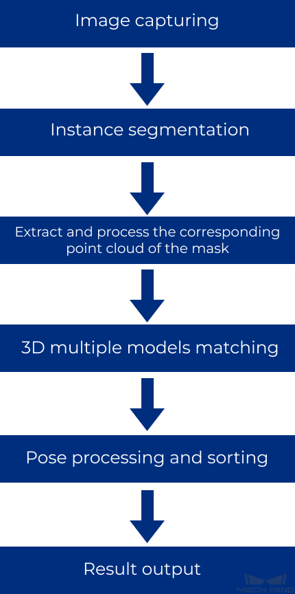
Image capturing: obtain the color image and depth map of the track shoes.
Instance segmentation: recognize the track shoes in the image via the deep learning algorithm, and obtain the pixel-wise mask.
Extract and process the corresponding point cloud of the mask: extract the point cloud corresponding to the track shoes’ mask, and perform point filtering, point cloud clustering, merging point cloud, and other processing.
3D multiple models matching: use the edge point cloud model of the track shoe’s front and back side obtained from point cloud preprocessing to match with the raw point clouds and obtain more accurate picking poses.
Pose processing and sorting: transform and sort the picking poses.
Result output: send the results of the current project to the backend service.
Project Difficulties
The front and back sides of the track shoes should be recognized.
The track shoes are stacked on each other, and part of the track shoes’ point cloud is missing
There is a strict requirement for the picking sequence of track shoes.
Project Advantages
Edge matching is used in this project, which increases the matching accuracy with the point cloud model.
Non-overlapping track shoes on the top layer can be recognized accurately.
Using a gripper with buffers in the picking direction significantly increases the picking success rate.
Project Deployment
Cautions
Deep Learning:
The deep learning model used in this project is a GPU model. If you want to run the project on site, you should use an industrial PC with a graphics card.
If you want to run the project on site, you should collect data and retrain the deep learning model.
Others:
This project is applicable to scenarios where the track shoes are placed with front and back sides alternately facing up.
If all infeed workpieces are placed with the back side facing up, you can replace all the multiple models matching Steps with normal single model matching Steps, and adjust the logic of sorting pick points.
Suggestions for Parameter Adjustment
Extract and Process the Corresponding Point Cloud of the Mask
Point Filter : Under the premise of ensuring the integrity of the flat point cloud, try to remove the points incoming the side elevation and other noise points, and finally obtain the list of the clustered point cloud.

Get Highest Layer Clouds : Please ensure that the track shoes’ point cloud on the top layer can be obtained, while reducing the output of the unnecessary point cloud on the lower layers.
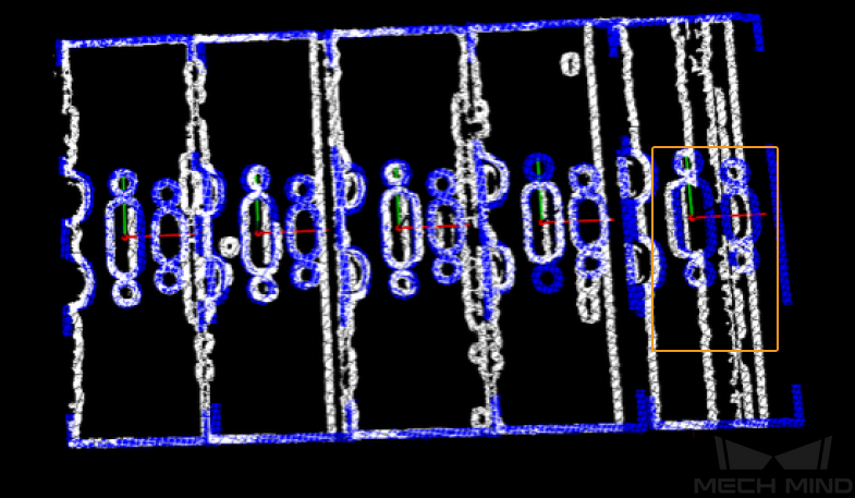
Estimate Point Cloud Edges by 2D Method : When the height of the workpiece stack is different, different 2D line width pixels need to be set (the default value is 15px). When the workpiece stack height is low (below 700mm), the matching effect is basically not affected; if the workpiece stack height is high, the edge width of the extracted point cloud changes greatly, which may affect the matching effect. You can try to set different 2D line widths at different heights Pixel resolved.
As shown in the figure below, the left shows the point cloud whose edge is to be extracted, and the right shows the extracted point cloud edge.

3D Multiple Models Matching
3D Fine Matching (Multiple Models) : The front side of the track shoe refers to the side with the metal bar facing up, while the other side refers to the back side. Please pay attention to the following issues during the 3D multiple models matching process.
Please set the corresponding Template Label File , select the ROTATE_BY_Z axis for the symmetrical rotation axis, and set the symmetrical angle step to 180.0° .
Please give priority to ensuring that there is no deviation when picking the uncovered workpiece on the top layer. For the workpiece on the lower layer that is overlapped, since there may be a missing part of the point cloud, a picking deviation is allowed.
Please set two edge point cloud models of the front and back side separately. Using the 2D method to extract the edge point cloud model with a line width aims to ensure the accuracy of the long-side direction of the track shoe, while using a full point cloud model for matching may lead to deviations in the long-side direction.
If the coarse matching deviation is too large to be further optimized by fine matching, it is recommended to adjust the coarse matching parameters first so that the rough matching deviation can be reduced. The common parameters you will need to adjust for coarse matching are Voxel Length and Sampling Interval. For example, when the sampling interval of point cloud model is 20 mm, the initial voxel length is recommended to be set to 10 mm. Then you can fine-tune the parameter according to the matching effect to determine the final voxel length. If the voxel length is set too small, it is likely to cause matching deviation.
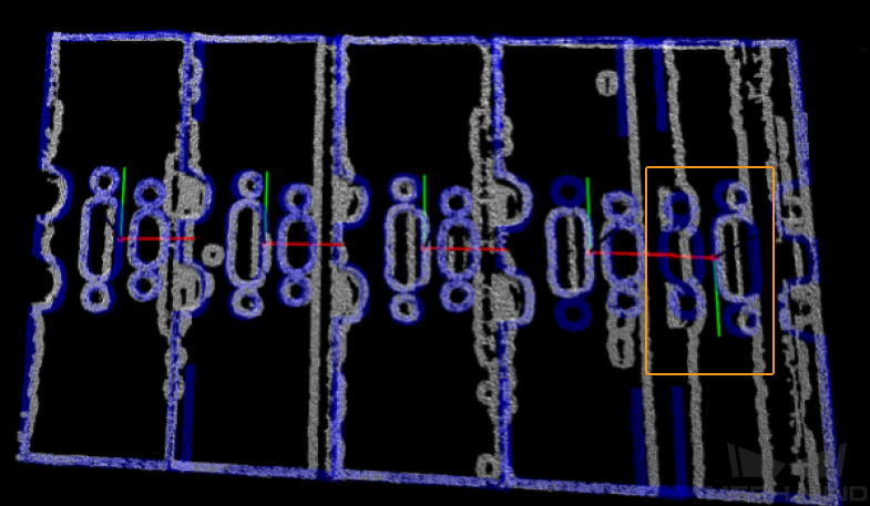
Remove Overlapped Objects : The Overlap Ratio Threshold cannot be set too small, and it is recommended to set it to 0.04. If the threshold is too small, all workpieces with overlapping point clouds will be filtered out at the same time. For example, if there are two workpieces in total, and the point clouds of the two workpieces overlap with each other, the poses of both workpieces will be filtered out, and there will be no output results.
As shown in the figure below, the white point cloud in the right figure is the overlapped workpiece that has been filtered out.

Pose Processing and Sorting
Get Highest-Layer Poses : If front-side workpieces are located on the top layer and lower layers, such as the second and third layers, only the poses of the front-side workpieces on the top layer should be kept, and this is also true for the back-side workpieces. If front-side workpieces are on both the top and second layers, sorting the poses of both layers may lead to errors.
The front-side and back-side workpieces are sorted according to the pose orientation: this Procedure can output the workpieces that need to be picked first on the higher layer based on the input poses of the back-side workpieces of this layer.
Because the placement of workpieces is regular, the adjacent workpieces on the same layer are in a stacked state. Assuming that there are four workpieces on a layer and the left to right direction is parallel to the long sides of the stack, from left to right, the first workpiece overlaps the second; the second workpiece overlaps the third, and so on. Under this circumstance, the first workpiece on the left should be picked first.
However, if the stack of workpieces rotates 180° when the material is incoming, and the first workpiece on the left becomes the first workpiece on the right, then the first workpiece on the right will be picked first. Therefore, after obtaining the poses of the back-side workpieces on the same layer, the orientation of poses determines the sorting method, and therefore the sequence of picking can be confirmed.
After the poses of the front-side and back-side workpieces are merged, only the poses of workpieces on the top layer will be output. If there is only one pose after the poses of the front-side and back-side workpieces are merged, the single pose will be output directly. If the poses of the front-side and back-side workpieces are merged, and two poses are output, one pose must belong to a front-side workpiece and the other must belong to a back-side workpiece. If the back-side workpiece is on the top of the front-side workpiece, the pose of the back-side workpiece will be higher than that of the front-side workpiece, and the height different between the two poses is close to the thickness of the metal bar of the track shoe. As for some abnormal conditions, a tilted stack may lead to an error when sorting the poses.
Numeric Operation : Subtract the approximate thickness of the metal bar from the Z value of the back-side track shoe.
Common Problems and Solutions
Inaccurate Matching Due to Poor Point Cloud Quality
When the matching is abnormal due to poor point cloud quality, the effect of matching abnormality is shown in the figure below.
At this time, the following optimization measures can be carried out:
Adjust camera parameters to improve point cloud quality.
According to the missing part of the point cloud, optimize the point cloud model of the workpiece to improve the matching stability.
After the optimization is completed, the matching effect is shown in the figure below.
Matching Errors or Abnormal Sorting Result of Picking Poses Due to Deep Learning Abnormalities
When abnormalities occur due to deep learning recognition, it may cause matching errors or abnormal sorting result of picking poses. Under this circumstance, the deep learning model can be iterated.