Brake Discs
This section provides guidance on using the Brake Discs project. The overview of the project is as follows.
Workpiece |
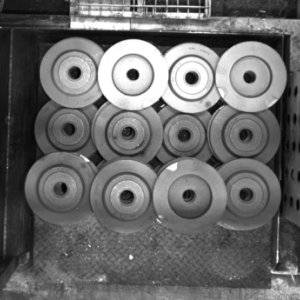
Brake discs, orderly arranged, with front and back sides alternately facing up |
Working distance |
1200–3000 mm |
Technical Specifications |
Recognition and positioning accuracy: ± 2 mm |
Recognition success rate: more than 99% |
|
Vision cycle time: within 5 s |
Project Description
The Brake Discs project is mainly used for picking brake discs that are orderly arranged.
The following section introduces the project in terms of applicable scenarios and technical specifications.
Applicable Scenarios
This section introduces the applicable scenarios of this project in terms of the workpiece, carrier, tool, and working distance.
Workpiece
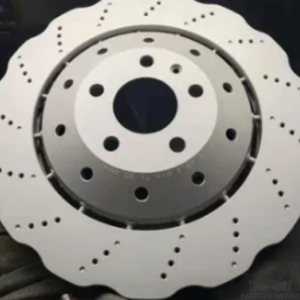
This project is applicable to brake discs with the following characteristics.
Workpiece Characteristic |
Application Case |
Example |
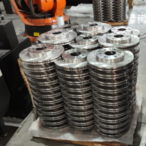
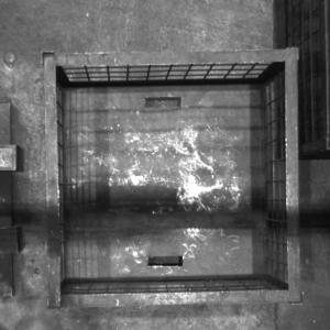
Condition of infeed workpieces |
Suitable for orderly arranged brake discs of the same specifications, and the brake discs can be placed with front and back sides alternately facing up |
|
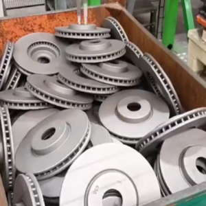
Not suitable for randomly stacked brake discs of different specifications |
|
|
Shape and size |
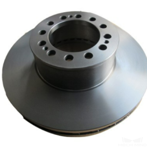
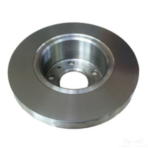
Suitable for disc-shaped brakes, and the concave and convexity of the front and back sides can be different |
|
|
||
Not suitable for non-disc-shaped brakes |
|
|
Material |
Cast iron |
|
Reflectivity |
A certain degree of reflection on the workpiece surface is allowed |
|
Point cloud quality |
The missing part of the scene point cloud should be less than 5% |
|
Carriers
This project is applicable to carriers with the following characteristics.
Carrier Characteristic |
Application Case |
Example |
Type of carrier |
Trays are recommended |
|
Suitable for bins as well, but collisions between the bin wall and the robot tool should be prevented |
|
|
Not suitable for bins with reflective or deformed walls |
Technical Specifications
The technical specifications of the Brake Discs solution are as follows.
Recognition and positioning accuracy: ± 2 mm
Recognition success rate: more than 99%
Vision cycle time: within 5 s
Note
Vision cycle time refers to the amount of time for the project to execute once, from image capturing to outputting vision result.
Solution Planning
Project Layout
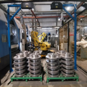
Workstation Layout
The layout of the workstation is shown below. The robot is at the center of the workstation, and the infeed area is located on the right rear side of the robot.
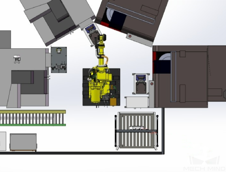
The workflow in the workstation is as follows:
The bin is moved to the infeed area by a manual forklift.
The upper system notices to the robot that the bin with brake discs is at the infeed area.
The robot sends an image-capturing command to the vision system, and the camera will be triggered to capture the image for recognition. Then the vision system sends the information about the brake discs’ positions and labels of the front and back sides to the robot.
Guided by the position information sent by the vision system, the robot picks the brake disc and places it on a platform for a second positioning.
Repeat the above steps until all the brake discs have been loaded.
Hardware of the Vision System
Recommended Specification |
Description |
|
Camera |
LSR L |
Recommended mounting method: Eye-to-Hand; working distance: 1200-3000 mm |
IPC |
Standard model without a GPU |
Processor: CPU Intel i5-12400 |
RAM: 16G DDR4 |
||
HDD: 256G SSD |
||
Power supply: DC24V 7.5A |
||
Operating system: Windows 10 64-bit |
||
WIFI module |
Robot Tool
There are two types of robot tools used in the Brake Discs project, which are the magnetic gripper and internal finger gripper.
Magnetic Gripper
The magnetic gripper is shown in the figure below.
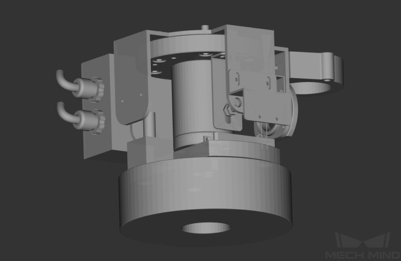
Gripper Description:
The magnetic gripper can directly attract the brake disc’s upper surface on the large circle or the small circle.
Gripper Advantages:
Adaptable to brake discs of various sizes.
Compatible with larger picking deviations and increases the picking success rate.
The picking method on both sides of the brake disc is the same, and the TCP setting is relatively simple.
Gripper Disadvantages:
Not suitable for brake discs with larger central holes.
Internal Finger Gripper
The internal finger gripper is shown in the figure below.
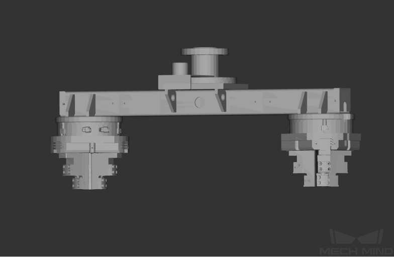
Gripper description:
The gripper grasps the brake disc from inside the central hole outward.
Gripper advantages:
With higher recognition and positioning accuracy and stability.
Long service life.
Gripper disadvantages:
Not suitable for brake discs with small central holes.
Higher requirements for recognition and positioning accuracy.
Different internal extension lengths of the gripper should be set for the front and back sides of different brake discs.
Vision Solutions
Communication Method
This solution usually uses Adapter communication.
The description of Adapter communication is as follows.
Robot -> IPC |
Request Command |
Mech-Vision Project ID |
Workpiece Model |
|
“P”: Request to capture images |
1–9 |
1–99 |
||
Example |
P, 1, 2 |
|||
Description |
Capture the image, project ID 1, workpiece model 2 |
|||
IPC -> Robot |
Status Code |
Workpiece Model |
Front and Back of the Workpiece |
Pick Point |
0: Recognition success 1: No workpiece 2: Recognition failure |
1–99 |
1: Front side 2: Back side |
X,Y,Z,A,B,C |
|
Example |
102, 1100, 1, 1, 0, 95.780, 644.567, 401.101, 91.120, -171.130, 180.0, 0, 0 |
|||
Description |
The photo was taken successfully, workpiece model 1, back side, pick point 1.574 , -0.443 , -1.122 , 43.12 , -24.25 , 179.66 |
|||
Project Description
The Brake Discs solution contains two projects: Vis_CreateModel (Project 1), Vis_BrakeDisc (Project 2).
Vis_CreateModel: Used to generate point cloud models and pick points. With Adapter communication method, you can create a point cloud model by entering the specification of the workpiece in the software or selecting a saved workpiece specification directly, and then the point cloud model and geometric center points will be automatically generated. The process is shown in the figure below.
Vis_BrakeDisc: Used to locate and recognize brake discs. Using the point cloud model generated from the Vis_CreateModel project, the brake discs can be located by 3D matching, and different point cloud models are used for different workpieces. The process is shown in the figure below.
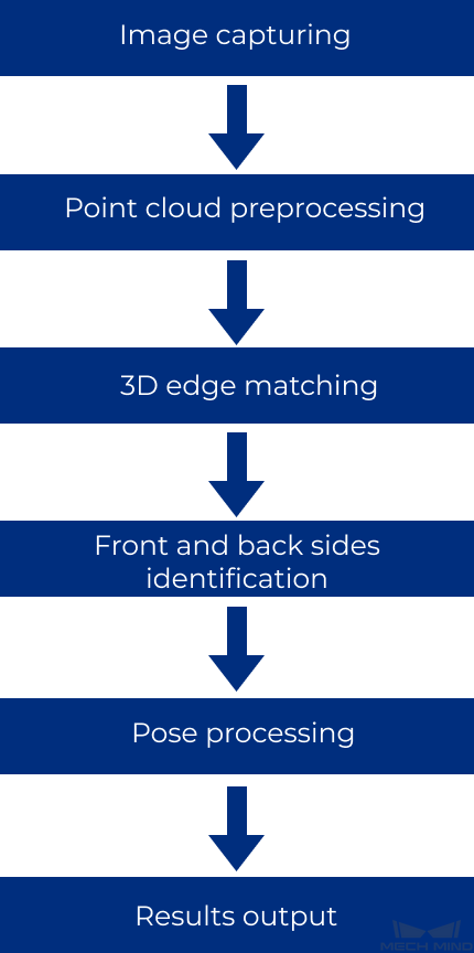
Image capturing: Obtain the color images and depth maps of the brake discs.
Point cloud preprocessing: Used to pre-process the original point cloud of the brake discs.
3D edge matching: Point cloud model matching by using the point cloud edge model of the brake discs.
Front and back sides identification: Used to distinguish the front and back sides of the brake discs.
Pose processing: Used to transform and sort the pick points of brake discs.
Results output: Send the results of the current project to the backend service.
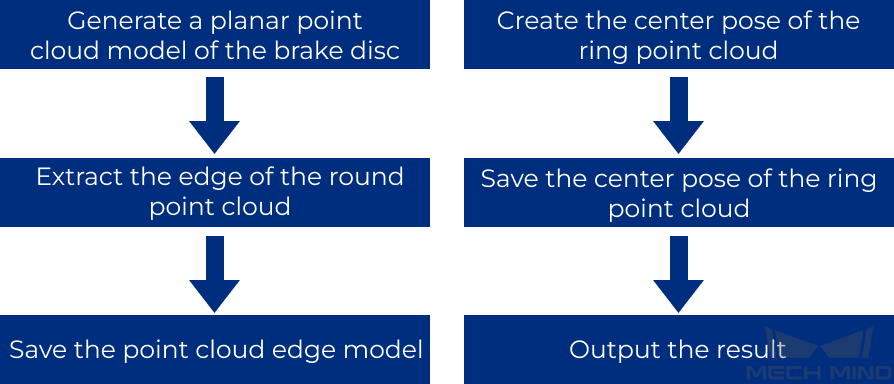
Generate Point Cloud Model and Add Pick Point
You can use Mech-Vision to create a point cloud model of a round shape first, and then extract the circular contour of the point cloud.
The center of the generated circle point cloud will be used as the geometric center point for matching.
Project Advantages
Convenient interactive interface. Make production more intelligent and convenient.
A point cloud model for matching can be automatically generated based on the workpiece size. After adding the brake disc model, you only need to add the brake disc size once.
Recognition stability is high. Using edge matching can effectively prevent misidentification and missed identification, and can stably identify the front and back sides of the brake disc.
Effective error-proofing Steps. Abnormal labels can be added to abnormal workpieces.
Project Difficulties
The front and back sides of the brake discs need to be identified.
There are many types of brake discs, and the point cloud model needs to be updated according to the actual size information.
The tray or shelf may be misidentified in the process of picking.
Project Deployment
Suggestions for Parameter Adjustment (Project 1)
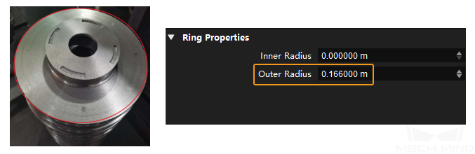
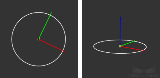
Create Object Model : Make the Outer Radius the same as the radius of the large circle of the brake discs (as shown on the left in the figure below).
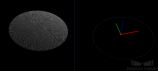
The relative positional relationship between the generated pick points and the point cloud model is shown in the figure below.
Suggestions for Parameter Adjustment (Project 2)
Point Cloud Preprocessing
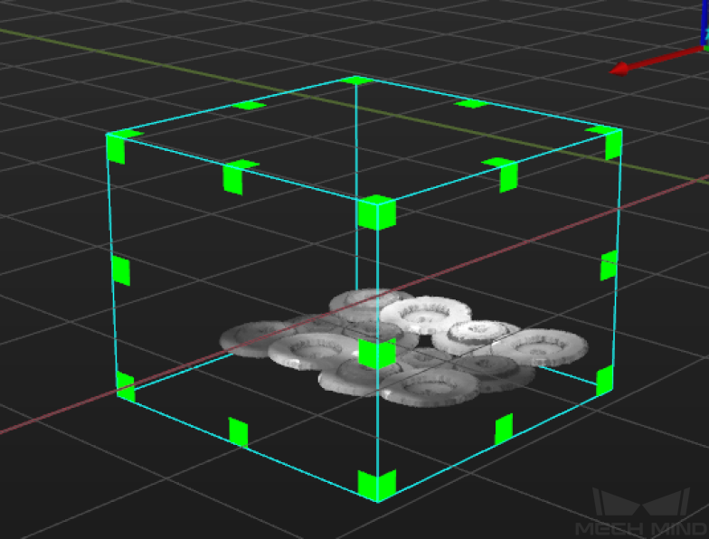
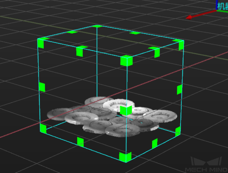
Extract 3D Points in 3D ROI : The 3D ROI needs to be set.
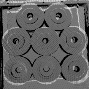
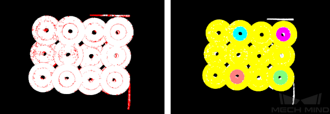
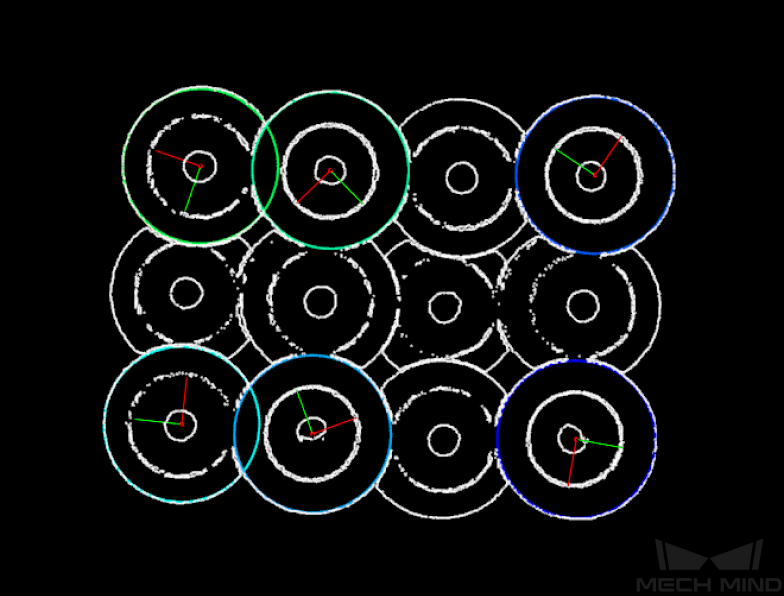
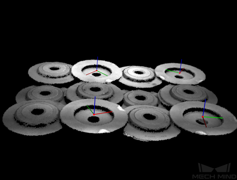
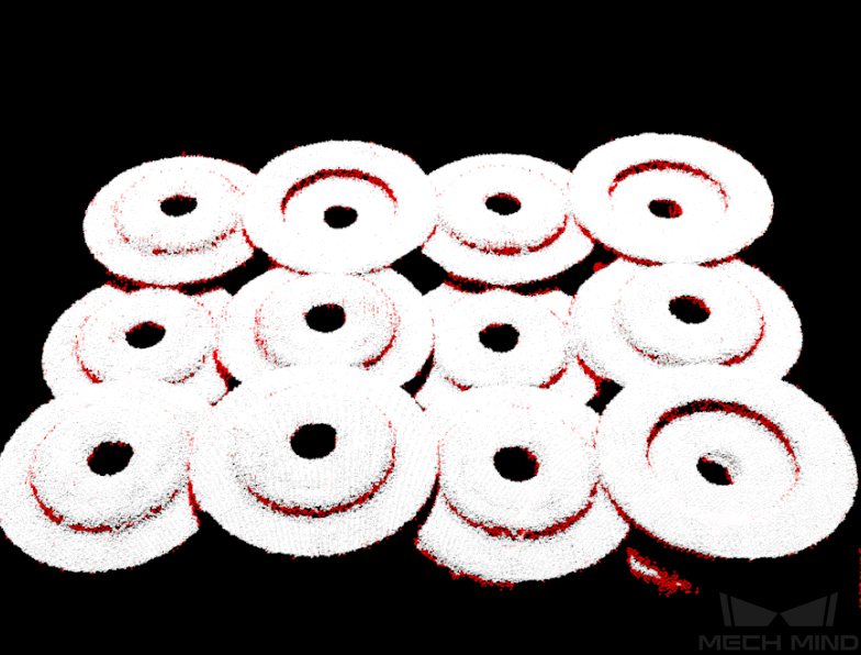
Point Filter and Point Cloud Clustering : The noise points need to be removed as much as possible, and only the point clouds of the brake discs should be retained. The visualization output results are shown in the figures below.
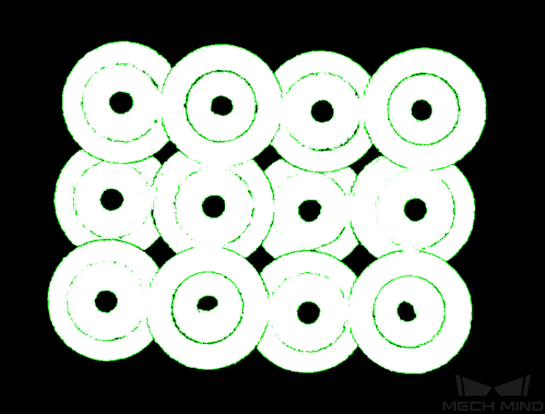
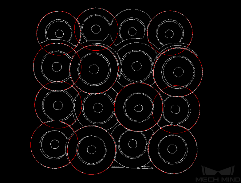
Estimate Point Cloud Edges by 3D Method : The point cloud of the brake disc’s outer ring needs to be extracted as complete as possible.
3D Edge Matching
3D Coarse Matching V2 : The file path of the model file and geometry center file needs to be the same as those saved in the Vis_CreateModel project.
3D Fine Matching : Please ensure that the workpieces on the top layer are all recognized, and it is acceptable that the workpieces on the lower layers are not all recognized.
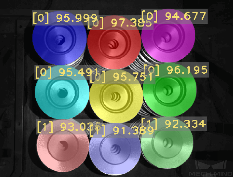
Identify the Front and Back Sides
Get Highest-Layer Poses : When the upper surface of the small circle on the convex side and the upper surface of the large circle on the concave side of the brake disc are similar in height, only the pose of the concave surface needs to be obtained.
Extract 3D Points in Cylinder : The parameters for this Step need to be set according to the brake disc size. When the convex side of the brake disc is facing up, the point cloud of the protruding small ring can be extracted. When the concave side of the brake disc is facing up, the point cloud extracted is theoretically empty. This distinguishes between the convex side (front sides) and the concave side (back sides) of the brake discs.
Dichotomize Values by Threshold : Please set a suitable threshold value to identify the front and back sides of the brake discs.
Pose Processing
Filtering out poses outside the ROI and the corresponding labels
Validate Existence of Poses in 3D ROI: An ROI should be set to filter out poses outside the ROI.
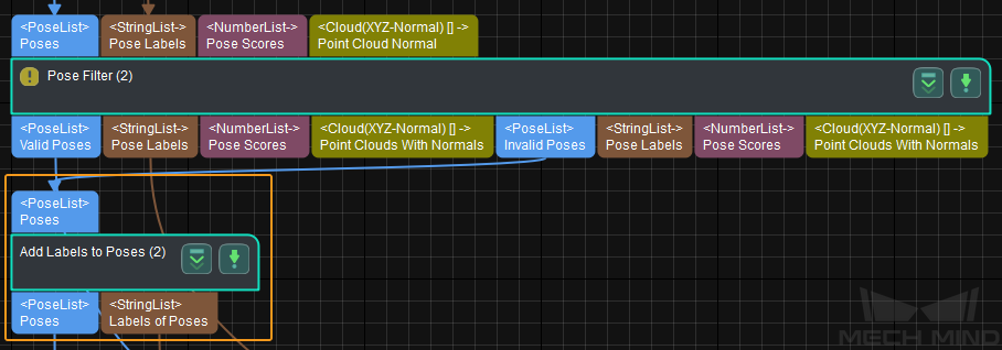
Pose Filter: You need to set the Angle Threshold and then add an exception label for the workpiece that exceeds the limit.
Common Problems and Solutions
No Recognition Result or Deviation Occurs
Method 1: Adjust the Point Cloud Preprocessing Procedure.
Check whether the Pose Filter Step has filtered out all points on the side of the point clouds and the upper surface of the point clouds are completely left, as shown in the figure below.
Check if the point cloud edges extracted by the Estimate Point Cloud Edges by 3D Method Step are complete.
If the result is not satisfactory, you can adjust the following parameters.
Search Radius
Min Angle, Max Angle
Angle Threshold, Search Number
Method 2: Check whether the size of the point cloud model corresponds with that of the actual point cloud of the brake disc.
Method 3: Adjust matching parameters.
You can focus on adjusting the Expected Point Count of Sampled Model , Referring Point Sampling Step, and Voxel Length parameters in the 3D Coarse Matching V2 Step.
Missing Point Cloud
If there is a large missing part on the point cloud of the brake disc, which results in unstable matching, it is recommended to add deep learning related Procedures after the Point Cloud Preprocessing Procedure for obtaining the mask of the brake disc and then performing matching.
Deep learning functions can be used to extract and segment a single mask, and then label the front and back sides of the brake disc.
Then the point cloud corresponding to the mask can be extracted, and point cloud model matching and recognition will be performed.