Generate Point Cloud Model
Point cloud model can not only describe the whole target object, but also describe part of the target object, such as the object’s surface or edge. A good point cloud model should meet at least the following 3 requirements:
The point cloud contains little noise or no noise.
The points in the point cloud distribute evenly, and the number of points are neither too many or too few.
The point cloud can well represent the features of the target object.
There are two ways for you to generate a point cloud model in Matching Model and Pick Point Editor:
Generate from Images Acquired by the Camera
This feature generates a point cloud from depth map(s) acquired by the camera.
Hint
This feature is available only when the opened project contains the Capture Images from Camera Step in which the Camera Settings parameters are fully configured.
The procedure differs when a real camera or virtual camera is used. Please read on to learn about detailed instructions.
Real Camera
When a real camera is used to acquire depth map(s) for making the point cloud model, the procedure differs depending on whether the background image can be captured separately. The detailed instructions are described as follows.
The Background Image Can Be Captured Separately
This procedure is applicable to objects that are easily movable, such as light and small workpieces.
Place the target object in the camera’s field of view:
If you have NOT added pick point(s) by teaching, place your target object directly in the camera’s field of view.
If you have already added pick point(s) by teaching, make sure the target object has not moved from then on (otherwise please redo adding pick point by teaching and ensure that the object doesn’t move afterwards).
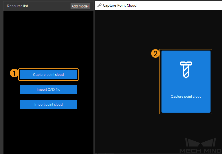
Click the Capture point cloud button in the start screen, and select Capture point cloud in the pop-up Capture Point Cloud window.
Select Use edge point cloud according to the actual requirement, and click Capture object to capture a depth map of the target object.

The captured depth map is shown as below. If you want to remove the background, click Remove background.

Remove all target objects in the camera’s field of view first, and click Capture background to capture a depth map of the background separately.

The depth map of the background is shown as below. Then click Next.

Click Remove background to generate a point cloud model of the target object.

Click Finish to import the point cloud model to Matching Model and Pick Point Editor.

Hint
Point count threshold is used to remove the noise on the depth map of the target object after removing the background. The larger the value, more noise will be removed.
If the target object in the point cloud is not intact, you can decrease the value here and then click Remove background to check the result.
If the point cloud contains too many points of the background, you can increase the value here and then click Remove background to check the result.
Hint
Double-click the model name in the Model files list to rename a point cloud model.
Due to factors like lighting variations in the images, the point cloud model generated from saved images is likely to contain unwanted points. You can trim the model during editing.
Hint
If you open this page by clicking the link in the “Add Pick Point by Teaching” section, you can use the Back button on your browser to return and continue reading the instructions in “Add Pick Point by Teaching”.
The Background Image Cannot Be Captured Separately
This procedure is applicable to objects that are NOT easily movable, such as wheel hubs.
Make sure the target object is in the camera’s field of view:
If you have already added pick point(s) by teaching, make sure the target object has not moved since (otherwise please redo adding pick point by teaching and ensure that the object doesn’t move afterwards).
Click the Capture point cloud button in the start screen, and select Capture point cloud in the pop-up Capture Point Cloud window.
Click Capture object, and click Finish to generate a point cloud model.
Virtual Camera
When using the virtual camera, since you will not be able to acquire images in real time, you need to get images collected previously ready for use.
Tip
If you’d like to use the Remove background option, both the background depth map and depth map containing the target object must be prepared. However, the background depth map doesn’t have to contain no target objects at all; it just needs to contain one fewer target object than the depth map of the target object.
Since the saved images were usually captured during picking, the number of target objects in the N image is one more than that of the N+1 image. Therefore, it is recommended to read the depth map containing the target object first and use the next image as the background depth map.
In Mech-Vision’s graphical programming workspace, select the Capture Images from Camera Step, and adjust the following in the Step Parameters tab:
For Data Path, select the parent folder of the folder containing the depth maps. For detailed instructions, please see Capture Images from Camera.
Set Play Mode to Repeat All, so that you can return to the first depth map when you reach the end.
Click in the menu bar to open the Matching Model and Pick Point Editor.
Click the Capture point cloud button in the start screen, and select Capture point cloud in the pop-up Capture Point Cloud window.
The follow-up instructions are similar to that of the Real Camera. Every time you click the Re-capture object button, one of the images in the folder will be read in sequence. Repeat the operation until the depth map displayed in the window meet the requirement.
Generate from Imported CAD Files
If you already have the CAD model file of the target object, you can import this file into Matching Model and Pick Point Editor, and generate a point cloud model from the CAD file.
Hint
Currently, only STL format is supported.
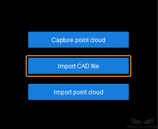
Click the Import CAD file button in the start screen, and select the CAD file you need and then click Open.
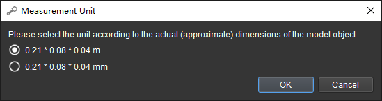
Select the measurement unit of the CAD model in the pop-up window.
The imported CAD file will show up in the CAD files list on the left.

Hint
Only one CAD file can be imported at a time. If you need to import multiple CAD files, please repeat steps 1 to 2.
Select the CAD file for point cloud model generation in the CAD files list, and then click
 or
or  on the toolbar to generate a point cloud model.
- : generate a point cloud of the entire surface of the CAD model.
After clicking, you will need to adjust the sampling interval for the point cloud in the pop-up window, and then click OK to generate the point cloud model.

- : generate a point cloud of only the part visible in the current view.
In the figure below, the left image is the view used for point cloud generation, and the right image is the generated point cloud. You can see that the point cloud doesn’t contain points from the part that is not visible in the left image.

Hint
Occasionally,
and may become disabled if you already have point cloud model(s) generated.In such cases, please click anywhere in the Editor interface to deselect the file in the CAD files list, and then reselect it. The above buttons should become enabled.
Hint
Other than generating point cloud models through the methods described above, you can also import existing point cloud files in PLY format directly by clicking Import point cloud button in the start screen.
The following are some actions you can take once you have generated a point cloud model:
Save all the files in the Lists: click or use the shortcut Ctrl + S.
Hint
Files are save to the following directory: Project Folder/resource/model_editor.
Delete a point cloud model: right-click the point cloud you wish to delete in the Model files list, and select Delete in the pop-up menu.
Toggle the visibility of a file: click
 to the right of the file name will make the file invisible in the visualizing space. Clicking again makes the file visible.
Show the bounding box: select a file in the Files List, and then check the box in front of Show bounding box below the CAD files list.
Change the display color of a point cloud: select a point cloud model in the Model files list, double-click the white rectangle next to Cloud color below the CAD files list, and then change the color in the pop-up window.
Hint
The display color of an imported color point cloud cannot be changed.
Now that you have a point cloud model, you can start editing it to meet your actual needs.